


Reference Manual
00809-0100-4388, Rev BA
January 2008
Rosemount 1153 Series D
2-2
MECHANICAL
CONSIDERATIONS
This section contains information you should consider when preparing to
mount the transmitter. Read this section carefully before proceeding to the
mechanical installation procedure.
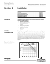
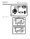
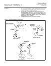
Mount the Rosemount 1153 Series D transmitter to a rigid support (a support
with a fundamental mechanical resonant frequency of 40 Hz or greater). A
mounting bracket included with the transmitter facilitates panel mounting.
Figure 2-4 on page 2-6 shows qualified transmitter mounting configurations.
The transmitter was seismic tested and qualified with the bracket mounted
using four
3
/8-in. diameter bolts. Orientation with respect to gravity is not
critical to qualification. However, if the transmitter is mounted with the flanges
in a horizontal position, rezero the transmitter to cancel the liquid head effect
caused by the difference in height of the process connections.
If you mount the transmitter to a non-rigid panel, ensure that seismic input to
the mounting bracket does not exceed qualification levels given in Rosemount
Report D8300040.
Process Connections Process tubing installation must prevent any added mechanical stress on the
transmitter under seismic disturbances. This may be done by using
stress-relief loops in the process tubing or by separately supporting the
process tubing close to the transmitter.
The process connections to the transmitter flanges were qualified with
3
/8-in.
tubing using compression fittings (Swagelok
®
). For options using
1
/4–18 NPT
connections, the user assumes responsibility for qualifying the interface.
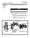
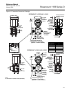
Transmitters with Flange Options A, D, H, J, L, or M are shipped with
Swagelok fittings for process connections. Included are front ferrule, rear
ferrule, and nut. Ensure that they are placed on the tubing with the orientation
and relative position shown in Detail A, Figure 2-5 on page 2-7.
Process tubing used is
3
/8-in. outside diameter, and of suitable thickness for
the pressure involved.
The Swagelok tube fittings come completely assembled and are ready for
immediate use. Do not disassemble them before use; because they may
become dirty or a foreign material get into the fitting and cause leaks. Insert
the tubing into the Swagelok tube fitting, making sure that the tubing rests
firmly on the shoulder of the fitting and that the nut is finger tight. Tighten the
nut one-and-one-quarter turns and it is ready for use. Do not overtighten.
The connections can be loosened and retightened 20–30 times without
compromising the leak-proof seal. To reconnect, insert the tubing with
pre-swaged ferrules into the fitting until the front ferrule sits in the fitting.
Tighten the nut by hand, then rotate one-quarter turn more or to the original
one-and-one-quarter tight position. Then snug it slightly with a wrench. For
more information regarding the use of Swagelok tube fittings, refer to:
Fittings Catalog MS-01-140
“Gaugeable Tube Fittings and Adapter Fittings”
www.swagelok.com
If the drain/vent valves must be opened to bleed process lines, torque them to
7
1
/2 ft-lb (10 N-m) when closing.