


Reference Manual
00809-0100-4388, Rev BA
January 2008
Rosemount 1153 Series D
3-8
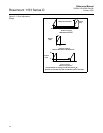
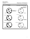
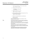
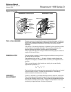
Figure 3-4. Linearity and
Damping Adjustment.
Damping Adjustment Damping electronics are available as an option. Transmitters with standard
electronics can be retrofitted with the adjustable damping feature by changing
out both the amplifier board (RMT P/N 01154-0021-0004) and the calibration
board (RMT P/N 01154-0023-0002).
The damping adjustment permits damping of rapid pressure variations by
adjusting the single-turn trim potentiometer located on the upper right-hand
side of the amplifier board (see Figure 3-4 on page 3-8). The available
settings, when adjusted to the maximum position, provide time-constant
values of at least 1.2 seconds for Range Code 4 and 0.8 seconds for Range
Codes 5–9. Transmitters with the electronic damping option are calibrated
and shipped with the adjustment set at the counterclockwise stop, giving the
minimum time-constant.
To adjust the damping, turn the damping adjustment potentiometer until the
desired time-constant is obtained. It is best to set the damping to the shortest
possible time-constant. Since transmitter calibration is not affected by the
damping setting, you may adjust the damping with the transmitter installed in
the process.
NOTE
If you remove either cover during the above procedures, replace the
O-ring and torque the cover per the instructions provided in Section 5
Maintenance and Troubleshooting. Spare cover O-rings are supplied with
each transmitter.
Damping Adjustment
(Optional on “R”
Electronics Only)
Linearity
Adjustment
Electronics Side of
Transmitter Housing
(Cover Removed)
The damping adjustment potentiometer has positive stops at both ends.
Forcing the potentiometer beyond the stops may cause permanent
damage.