


Reference Manual
00809-0100-4388, Rev BA
January 2008
3-5
Rosemount 1153 Series D
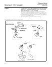
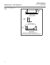
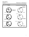
B1. Method (Output Code P—Amplifier Board with Holes)
a. Cut the jumper wire, form, and insert across 2 jumper pads on the
component side of the board in the “elevate zero” position (see
Figure 3-3 (Detail A2) on Page 3-7).
b. Turn the board over and clip the wire ends to the appropriate
length. In accordance with proper electronic practices, solder the
jumper wire to the board. Clean solder joints with isopropyl alcohol.
c. Plug the amplifier board back in and complete the zero adjustment.
To suppress zero follow the same procedure except position the jumper wire
on the board in the “suppress zero” position (see Figure 3-3 (Detail A3) on
Page 3-7).
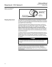
B2. Method (Output Code R and Output Code P—Amplifier Board with
Turrets)
a. Locate 3 turret terminals on the component side of the amplifier
board. Remove any jumper wires between them (Figure 3-3 on
page 3-7).
b. To elevate zero, connect a jumper wire between the middle
terminal and the terminal marked “EZ” (see Figure 3-3 (Detail B2)
on Page 3-7).
c. Wrap the jumper wire once around each terminal and cut off the
excess.
d. Solder the jumper wire to the terminals using proper electronics
soldering techniques. Clean solder joints thoroughly with isopropyl
alcohol.
e. Plug the amplifier board back in and complete the zero adjustment.
To suppress zero, follow the same procedure, except connect the jumper wire
between the middle terminal and the terminal marked “SZ” (see Figure 3-3
(Detail B3) on Page 3-7).
6. Recheck full scale and zero and fine tune if necessary.
NOTE
There is some mechanical backlash in the zero and span adjustments, so
there will be a dead band when you change the direction of adjustment.
Because of the backlash, the simplest procedure, if the desired setting is
overshot, is to intentionally overshoot a larger amount before reversing the
direction of the adjustment.
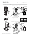
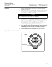
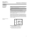
Linearity Adjustment In addition to the span and zero adjustments, there is a linearity adjustment
located inside the transmitter on the amplifier board (see Figure 3-4 on
page 3-8). Linearity is factory calibrated for optimum performance over the
calibrated range of the instrument and is not normally adjusted in the field. If
you want to maximize linearity over some particular range, use the following
procedure: