


Reference Manual
00809-0100-4388, Rev BA
January 2008
Rosemount 1153 Series D
5-6
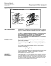
Process Flange
Reassembly
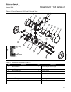
1. Replace the metal O-rings (11) with new O-rings if the flanges were
removed.
2. Carefully place an O-ring (11) in the isolator well of the high side (“H”)
of the sensing module. Place the O-ring so the edge of the rolled ring
faces the module. (See Detail A of Figure 5-2 on page 5-7).
3. Carefully place the flange (13 or 15) as shown in Figure 5-2 on
page 5-7. Take care not to disturb the O-rings or damage the
diaphragms.
4. On differential units, repeat steps 2 and 3 for the low side (“L”) of the
module. If a gage unit has two O-rings (one on each side), repeat
steps 2 and 3 for the low side. If the gage unit has only one O-ring,
reassemble with one O-ring on the high side.
5. Keeping the flanges parallel to each other and to the module faces,
insert the four bolts (14) (and four washers on Range 9) and
finger-tighten the nuts (8).
Each spare bolts and nuts parts kit contains the correct number of
nuts, bolts and washers for the specific transmitter range code it is
designated for. Due to consolidation of parts kits, the bolt length and
quantity of washers required may differ for existing transmitter
assemblies and/or parts kits. Verify by part number that the
appropriate spare parts kit is used for the transmitter range code
being re-assembled. Contact Rosemount Nuclear Instruments, Inc. if
there are questions.
6. Evenly seat the flanges on the sensor module housing, using a hand
torque wrench as specified in steps 7 through 11. See Figure 5-2 on
page 5-7 to identify the bolts.
7. Alternately tighten bolts A and B to 10 ft-lb (14 N-m) torque.
8. Alternately tighten bolts C and D to 10 ft-lb (14 N-m) torque.
9. Check the torque on bolts A and B.
10. Check the torque on bolts C and D.
11. Repeat steps 7–10 at 15 ft-lb (20 N-m) torque, at 20 ft-lb (27 N-m)
torque, at 25 ft-lb (34 N-m) torque, at 30 ft-lb (41 N-m) torque, and at
35 ft-lb (48 N-m) torque until all bolts are torqued to
35 ±1 ft-lb (48 ±1.4 N-m).
12. Expose all ranges of absolute and gage transmitters to two
temperature cycles over the expected temperature operating range
before calibrating. Expose differential and high-line differential range
3’s and 4’s to two temperature cycles over the expected temperature
operating range before calibrating.
POST-ASSEMBLY TESTS 1. Conduct hydrostatic testing to 150% of maximum working pressure or
2,000 psi, whichever is greater.
2. Calibrate the transmitter per the calibration section of this manual.
3. Conduct nuclear cleaning to one ppm chloride content of transmitter
“wetted parts.”