


Reference Manual
00809-0100-4388, Rev BA
January 2008
Rosemount 1153 Series D
www.rosemountnuclear.com
Index
A
About The Transmitter . . . . . . 1-1
B
Board Checkout . . . . . . . . . . . 5-2
Both Output Codes . . . . . . . . 6-2
C
Calibration . . . . . . . . . . . . . . . 3-1
Calibration Procedures . . . . . . 3-3
Conduit Connection . . . . . . . . 2-4
Connecting Electrical Housing to
Sensor Module
. . . . . . . . . . . 5-5
Correction For High Line Pressure
(Rosemount 1153DD and 1153HD
Only)
. . . . . . . . . . . . . . . . . . 3-9
Current Control . . . . . . . . . . . 4-4
Current Limit . . . . . . . . . . . . . 4-4
D
Damping Adjustment . . . . . . . 3-8
Demodulator . . . . . . . . . . . . . 4-3
Dimensional Drawings . . . . . . 2-7
Disassembly Procedure . . . . . 5-3
E
Electrical . . . . . . . . . . . . . . . . 2-9
Electrical Block Diagram . . . . . 4-2
Electrical Considerations . . . . 2-4
Electrical Housing Disassembly 5-4
Electrical Housing Reassembly 5-5
F
Functional Specifications . . . . 6-6
G
General Considerations . . . . . 2-1
H
Humidity Limits . . . . . . . . . . . 6-7
I
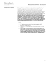
Important Notice . . . . . . . . . 6-13
Installation Procedure . . . . . . . 2-6
Introduction . . . . . . . . . . . . . . 1-1
J
Jumper Wire Placement . . . . . 3-7
L
Linearity Adjustment . . . .3-5, 4-3
Load Effect . . . . . . . . . . . . . . 6-5
Load Limits . . . . . . . . . . . . . . 6-6
M
Materials of Construction . . . . 6-8
Maximum Working Pressure . . 6-7
Mechanical Considerations . . . 2-2
Mounting Position Effect . . . . 6-5
N
Nuclear Specifications . . . . . . 6-1
O
Oscillator . . . . . . . . . . . . . . . 4-4
Output Code P . . . . . . . . . . . 6-1
Output Code R . . . . . . . . . . . 6-1
Overview . . . . . . . . . . . . . . . 4-1
P
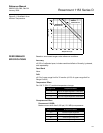
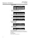
Performance Specifications . . 6-3
Physical Specifications . . . . . 6-8
Post-assembly Tests . . . . . . . 5-6
Power Supply Effect . . . . . . . 6-4
Preliminary . . . . . . . . . . . . . . 5-5
Pressure Ranges . . . . . . . . . 6-7
Process Connections . . . . . . . 2-2
Process Flange Reassembly . 5-6
Process Flange Removal . . . . 5-3
Q
Qualified Life vs. Ambient Temperature
. . . . . . . . . . . . . . . . . . .2-1, 6-3
R
Reassembly Procedure . . . . . 5-4
Removing Sensor Module from
Electrical Housing
. . . . . . . . . 5-4
Response Time . . . . . . . . . . . 6-5
Reverse Polarity Protection . . 4-4
Rosemount 1153 Series D Parts List
5-7
Rosemount 1153 Series D Spare Parts
List
. . . . . . . . . . . . . . . . . . 6-11
S
Safety Messages . . . . . . . . . .5-1
Sensing Module Checkout . . . .5-2
Span . . . . . . . . . . . . . . . . . . .3-9
Span Adjustment . . . . . . . . . .3-1
Span and Zero . . . . . . . . . . . .6-6
Spare Parts Shelf Life . . . . . .6-12
Static Pressure and Overpressure
Limits
. . . . . . . . . . . . . . . . . .6-8
Static Pressure Span Effect . . .6-4
T
Temperature Limits . . . . . . . . .6-6
Test Terminals . . . . . . . . . . . .5-2
The d-Cell . . . . . . . . . . . . . . .4-3
The d-Cell Sensor . . . . . . . . . .4-3
Torque References . . . . . . . . .5-8
Transmitter Design Specifications .
6-10
Transmitter Installation Configurations
2-8
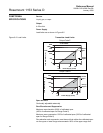
Transmitter Load Limits Graph .2-5
Transmitter Operation . . . . . . .4-1
Transmitter Terminal Block . . .2-9
Transmitter Wiring Connections
Diagram
. . . . . . . . . . . . . . . . .2-5
Troubleshooting . . . . . . . . . . .5-9
Turn-On Time . . . . . . . . . . . . .6-7
Typical Rosemount 1153 Series D
Exploded View
. . . . . . . . . . . .5-7
Typical Transmitter Mounting Bracket
Configuration . . . . . . . . . . . . .2-6
V
Voltage Regulator . . . . . . . . . .4-4
Volumetric Displacement . . . . .6-7
Z
Zero . . . . . . . . . . . . . . . . . .3-11
Zero Adjustment . . . . . . . . . . .3-1
Zero Adjustment Range . . . . . .3-2
Zero And Span Adjustments . .4-4
Zero Elevation and Suppression 6-6