


Reference Manual
00809-0100-4388, Rev BA
January 2008
Rosemount 1153 Series D
4-2
K
1
is a constant.
C
1
is the capacitance between the high pressure side and the sensing
diaphragm.
C
2
is the capacitance between the low pressure side and the sensing
diaphragm.
Where:
I
ref
is the current source.
V
p-p
is the peak-to-peak oscillation voltage.
f is the oscillation frequency.
Where:
I
diff
is the difference in current between C
1
and C
2
.
Therefore:
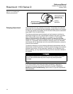
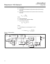
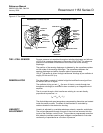
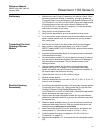
Figure 4-1. Electrical Block
Diagram.
fV
pp
–
I
ref
C
1
C
2
+
----------------------=
I
diff
fV
pp
–
C
2
C
1
–()=
PConstantI
diff
× I
ref
C
2
C
1
–
C
2
C
1
+
----------------------
⎝⎠
⎜⎟
⎛⎞
==
Sensor
Demodulator
Current
Detector
Oscillator
Osc.
Control
Amp.
Voltage
Regulator
Curr.
Control
Amp.
Current
Control
Current
Limiter
Reverse
Polarity
Protection
Signal
Test
–
–
–
+
+