


Reference Manual
00809-0100-4388, Rev BA
January 2008
3-11
Rosemount 1153 Series D
1. Using standard calibration procedures, calibrate the unit to the
required span, with the 4 mA or zero point corresponding to zero
differential pressure:
4 mA at 0 inH
2
O and 20 mA at 400 inH
2
O
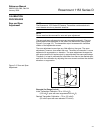
2. Apply static pressure to both high and low process connections with
zero differential pressure across the transmitter, and note the zero
correction (zero shift). For example, if the output reads 4.006 mA, the
zero correction is calculated as:
4.00 mA – 4.006 mA = –0.006 mA
Note the sign associated with this correction, as this result is added
when determining the final, ideal transmitter output.
3. Remove static pressure and correct for the span effect as outlined in
the span correction procedure. Calibrate the unit to the calculated
output values. If, for example, the span correction procedure yielded
4.029 mA and 20.144 mA, calibrate the unit for:
4.029 mA at 100 inH
2
O
20.144 mA at 500 inH
2
O
4. Add the zero correction (–0.006 mA), found in step 2, to the ideal zero
point value calculated in step 3.
4.029 mA + (–0.006 mA) = 4.023 mA
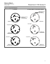
5. To eliminate the zero effect, readjust the zero potentiometer so the
output reads the ideal zero point calculated in step 4 (do not readjust
the span potentiometer). Note that all the calibration points will shift
the same amount toward the correct reading. The example output is
now 4.023 mA at 100 inH
2
O.
The transmitter output is now 4–20 mA over its calibrated span when
the unit is operated at 1,200 psi static line pressure.