


Reference Manual
00809-0100-4388, Rev BA
January 2008
3-9
Rosemount 1153 Series D
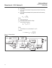
Correction For High Line
Pressure (Rosemount
1153DD and 1153HD
Only)
Span
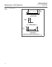
If a differential transmitter is calibrated with the low side at ambient pressure
but will be used at high line pressure, correct the span adjustment to
compensate for the effect of static pressure on the unit. If zero is elevated or
suppressed, also correct the zero adjustment. Correction factors, expressed
in percent of differential pressure input at end points per 1,000 psi static
pressure, are:
Range 3:
+1.5% of input/1,000 psi
Ranges 4, 5, and 8:
+0.75% of input/1,000 psi
Ranges 6 and 7:
+1.25% of input/1,000 psi
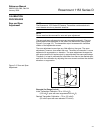
The correction procedure below uses the following example: Range 5,
calibrated –100 to 300 inH
2
O to be operated at 1,200 psi line pressure. Note
that steps 3–6 are omitted for ranges based at zero differential pressure.
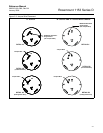
1. Calibrate the unit per preceding section to output = 4 mA at
–100 inH
2
O and 20 mA at 300 inH
2
O.
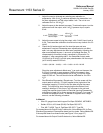
2. Calculate correction factor:
3. Calculate zero adjustment correction in terms of pressure:
4. Convert pressure correction to percent of input span:
5. Calculate correction in terms of output span (mA):
6. Add the milliamp correction to the ideal zero output (4 mA). This is the
corrected ideal zero output:
0.75 %
1,000 psi
------------------------ 1200 psi 0.9% differential input=×
0.9 % 100 inH
2
–× O 0.9 inH
2
O–=
0.9 inH
2
O–
400 inH
2
O input span
----------------------------------------------------------- 0.225 % span–=
0.225 % 16 mA span×– 0.036 mA–=
4.00 mA 0.036 3.964 mA=–