


Reference Manual
00809-0100-4388, Rev BA
January 2008
Rosemount 1153 Series D
3-4
1. Adjust the zero to eliminate any existing zero elevation or
suppression. With 0 inH
2
O pressure applied to the transmitter, turn
the zero adjustment until the output reads 4 mA. The unit is now
calibrated for 0 to 100 inH
2
O.
2. Adjust the span to the desired new span. To reduce the span, turn the
span screw until the output, with 0 inH
2
O pressure input, equals
8 mA:
3. Adjust the zero screw to bring the output, with 0 inH
2
O input, back to
4 mA. The transmitter calibration should now be very close to 0 to 50
inH
2
O.
4. Check the full-scale output and fine tune the span and zero
adjustment if required. Remember zero adjustments do not affect
span, but span adjustments do affect zero predictably. Adjusting the
span screw affects the zero
1
/5 as much as it affects the span. To
compensate for this effect, simply overadjust by 25 percent. For
example, if, after completing step 3, the transmitter output reads
19.900 mA at 50 inH
2
O, turn the span potentiometer until the output
(at 50 inH
2
O) reads 20.025 mA.
Since the span adjustment affects zero
1
/5 as much as the span, the
0.125 mA increase in span causes a 0.025 mA increase in zero.
Therefore, turn the zero adjustment (at 50 inH
2
O) until the output
reads 20.000 mA. The unit should now be calibrated for 0 to 50 in
H
2
O.
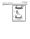
5. Zero Elevation/Suppression. Elevate zero. Turn the screw until the
output reads 4 mA with –75 inH
2
O applied to the high side of the
transmitter (applying 75 inH
2
O to the low side will give the same
result). The output may stop changing before the desired 4 mA
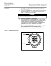
reading is obtained. If this occurs, turn off power to the unit and
unplug the amplifier board (refer to Electrical Housing Disassembly
procedure on page 5-4 for cover removal and Figure 5-2 on page 5-7
to locate the amplifier board). To elevate or suppress zero a large
amount, use the following procedure:
A. Material
• Wire: 22 gauge tinned solid copper-Fed Spec QQW343, ASTM B33.
• Solder: 60% tin, 40% lead (60/40)-Fed Spec QQ-S-571.
• Flux: Mil F 14256, Type A, Fed Spec QQ-S-571 Type RA.
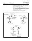
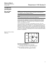
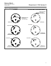
For transmitters with Output Code P electronics, follow Method B1 for Zero
Elevation/Suppression if the amplifier board has four holes. Follow Method B2
if the amplifier board has three turrets (see Figure 3-3 on page 3-7).
For transmitters with Output Code R electronics, follow Method B2.
4 mA
Existing Span
Desired Span
------------------------------------
× 4 mA
100 inH
2
O
50 inH
2
O
-------------------------------
× 8 mA==
19.900 + (20.000 – 19.900) ϫ 1.25 = 19.900 + 0.125 = 20.025