


Reference Manual
00809-0100-4388, Rev BA
January 2008
Rosemount 1153 Series D
2-6
INSTALLATION
PROCEDURES
Installation consists of mounting the transmitter and conduit and making
electrical connections. Following are procedures for each operation.
Mechanical
Transmitter
The threaded interface between the sensor module and the electronics
housing is hermetically sealed before shipment. The integrity of this seal is
necessary for the safe operation of the transmitter during accident conditions.
If the seal is broken, reseal it according to “Connecting Electrical Housing to
Sensor Module” on page 5-5.
1. Mount the bracket to a panel or other flat surface (see Figure 2-4 on
page 2-6). Use four
3
/8-in. diameter bolts (not supplied with unit). SAE
grade 2 bolts were used during qualification testing. Torque each bolt
to 19 ft-lb (26 N-m).
2. Attach the transmitter to the mounting bracket (see Figure 2-4 on
page 2-6). Use four
7
/16–20 ϫ
3
/4 bolts with washers (supplied with
unit). Torque each bolt to 21 ft-lb (29 N-m).
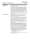
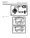
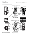
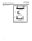
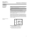
Figure 2-4. Typical Transmitter Mounting Bracket Configuration.
Be careful not to break the neck seal between the sensor module and the
electronics housing.
PANEL MOUNTING
HOLE PATTERN
(BACK SIDE)
Center of Gravity
(Bracket Included)
2.81
(71.4)
5
(127)
1.2
(30)
2.3
(58)
2.75
(69.9)
10 (254) Minimum
Clearance
3
/8-in.
Bolts (4)
(Customer
Supplied)
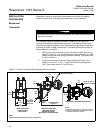
ACCEPTABLE ALTERNATE MOUNTING
2.3
(58)
NOTE
All dimensions are nominal in inches (millimeters).
Center of Gravity
(Bracket Included)
1.8
(45.7)
MOUNTING BRACKET
FOR PANEL MOUNT
SHOWN IN TYPICAL
MOUNTING CONFIGURATION
NOTES
1. Orientation with respect to gravity is not critical.
2. Units can alternately be mounted with process
connection adjacent to bracket.
4.93
(125)
2.81
(71.4)