


Reference Manual
00809-0100-4388, Rev BA
January 2008
Rosemount 1153 Series D
5-4
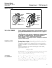
Electrical Housing
Disassembly
1. The signal terminals and test terminals are accessible by unscrewing
the cover (1) on the terminal side. This compartment is identified as
“terminal side” on the nameplate. The terminals are permanently
attached to the housing and must not be removed.
2. Circuit boards are located in a separate compartment identified as
“Circuit Side” on the nameplate. Remove power from the transmitter
before removing the circuit side cover. Unscrew the cover (1) on the
circuit side to access the circuit boards. A special cover wrench (RMT
P/N 01153-0382-0001) is available from Rosemount to remove and
replace the housing covers.
3. Unplug the amplifier board (6) after removing three holding screws
(7).
4. The header assembly board (4) is permanently attached to the sensor
module (12) and contains the temperature-compensating resistors.
Carefully pull this board off the bayonet pins and rotate the board 180
degrees about the axis formed by the connecting leads. This allows
access to the calibration board (5).
5. Disconnect the calibration board (5) by aligning the zero and span
adjust screws so that their slots are perpendicular to the board.
Remove the board by inserting a 6–32 screw in the rivnut on the
board and carefully pulling the board off the bayonet pins.
6. If replacement of the zero and span adjustment screws (16) is
necessary, remove the nameplate (17) and detach the snap rings (18)
inside the housing.
Removing Sensor
Module from Electrical
Housing
1. Remove flanges per “Process Flange Removal” on page 5-3.
2. Remove amplifier board and calibration board as described in the
“Electrical Housing Disassembly Section” above.
3. Loosen the lock nut (9).
4. Unscrew the sensor module (12) from the electronics housing,
simultaneously turning the header board and leads to prevent them
from being twisted or damaged. The threaded connection has a
sealing compound on it and must be broken loose. Be careful not to
damage the isolating diaphragms when unscrewing the sensor
module. Then carefully pull the header assembly board (4) through
the hole.
5. The sensor module (12) is a welded assembly and cannot be further
disassembled.
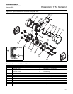
REASSEMBLY
PROCEDURE
NOTE
Numbers in parentheses refer to item numbers in Figure 5-2 on page 5-7.
NOTE
The Rosemount 1153 Series D Pressure Transmitter contains electronic
circuit boards which may be static sensitive.