


Reference Manual
00809-0100-4388, Rev BA
January 2008
Rosemount 1153 Series D
2-4
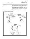
For differential transmitters, also consider the following:
• Keep both impulse legs at the same temperature.
• When using sealing fluid, fill both piping legs to the same level.
• When purging, make the purge connection close to the process taps
and purge through equal lengths of the same size tubing. Avoid purging
through the transmitter.
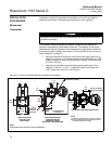
Conduit The conduit connection to the transmitter is
1
/2–14 NPT. Use a qualified
conduit seal at the conduit entry to prevent moisture from accumulating in the
terminal side of the housing during accident conditions. To prevent the conduit
from adding mechanical stress to the transmitter during seismic disturbances,
use flexible conduit or support the conduit near the transmitter. Install the
conduit seal in accordance with the manufacturer’s instructions or use the
procedure on page 2-8.
ELECTRICAL
CONSIDERATIONS
This section contains information that you should consider when preparing to
make electrical connections to the transmitter. Read this section carefully
before proceeding to the electrical installation procedures.
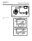
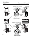
The Rosemount 1153 Series D pressure transmitter provides a 4–20 mA
signal when connected to a suitable dc power source. Figure 2-2 on page 2-5
illustrates a typical signal loop consisting of transmitter, power supply, and
various receivers (i.e., controller, indicator, computer). The power supply must
supply at least 12 volts to the transmitter terminals at 30 mA (overscale)
signal, or the maximum output current required for proper system operation.
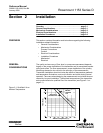
Any power supply ripple appears in the output load. The supply voltage
versus load limitation relationship is shown in Figure 2-3 on page 2-5. See
qualification report D8300040 for details. The load is the sum of the resistance
of the signal leads and the load resistance of the receivers.
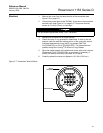
Signal wiring need not be shielded, but twisted pairs yield the best results. In
electrically noisy environments, shielded cable should be used for best
results. Do not run signal wiring in conduit or open trays with power wiring, or
near heavy electrical equipment. Signal wiring may be ungrounded (floating)
or grounded at any place in the signal loop. The transmitter case may be
grounded or ungrounded.
The capacitance-sensing element uses alternating current to generate a
capacitance signal. This alternating current is developed in an oscillator circuit
with a frequency of 32,000 ±10,000 Hz. This 32,000 Hz signal is capacitor
coupled to transmitter case ground through the sensing element. Because of
this coupling, a voltage may be imposed across the load, depending on
choice of grounding.
This impressed voltage, which is seen as high-frequency noise, has no effect
on most instruments. Computers with short sampling times in a circuit where
the negative transmitter terminal is grounded will detect a significant noise
signal. Filter this noise with a large capacitor (1 µf) or by using a 32,000 Hz LC
filter across the load. Signal loops grounded at any other point are negligibly
affected by this noise and do not need filtering.