


Reference Manual
00809-0100-4388, Rev BA
January 2008
2-7
Rosemount 1153 Series D
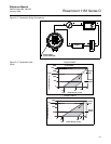
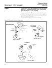
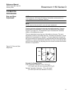
Figure 2-5. Transmitter Dimensional Drawings.
Low Side
Vent
(GD only)
7
/16–20
UNF
(Typical)
9 Max.
(228.6)
4.7 Max. (119.4)
4.72 Max.
(119.9)
3.4
(86.4)
7
/16–14 UNC
(4 Places)
Nameplate
(Remove for
Zero and Span
Adjust)
Transmitter
Circuitry
(this Side)
Terminal
Connections
(this Side)
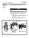
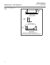
Dim
A
0.8 (20) to End
of Mating Tubing
Compression Fittings (1)
Swagelok for
3
/8-in. Tubing
(Optional
1
/4–18 NPT Available)
Welded
Drain/Vent
Valve (1)
(Optional
1
/4–18 NPT
Available)
Low Side
Vent
(GD only)
DETAIL A
3
/8-in.
Mating
Tubing
0.8
(20)
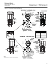
Welded
Drain/Vent Valve
(2) (Optional
1
/4–18 NPT
Dim.
A
1.63
(41.3)
7
/16–20
UNF
(Typical)
9 Max.
(228.6)
3.7
(94)
4.7 Max. (119.4)
4.72 Max. (119.9)
3.4
(86.4)
7
/16–14 UNC
(4 Places)
Nameplate
(Remove for
Zero and Span
Adjust)
Transmitter
Circuitry
(this Side)
Terminal
Connections
(this Side)
0.8 (20) to End
of Mating Tubing
Compression Fittings (2)
Swagelok
®
for
3
/8-in. Tubing
(Optional
1
/4–18 NPT Available)
Pressure
Range Code
Dimension
A
3, 4, 5 2.13 (54)
6, 7 2.19 (55.6)
8 2.25 (57.2)
9 2.28 (57.9)
0 2.33 (59.1)
ROSEMOUNT 1153DD AND 1153HD
ROSEMOUNT 1153AD AND 1153GD
3.7
(94)
1
/2–14 NPT
Conduit
Connection
(1 place)
1
/2–14 NPT
Conduit
Connection
(1 place)
0.75 (19) Clearance
for Cover Removal
(Typical)
0.75 (19) Clearance
for Cover Removal
(Typical)
1.63
(41.3)
NOTE
All dimensions are nominal in inches (millimeters).