


Reference Manual
00809-0100-4388, Rev BA
January 2008
5-9
Rosemount 1153 Series D
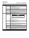
Table 5-3. Troubleshooting.
Symptom Potential Source Corrective Action
High Output Primary Element Check for restrictions at primary element, improper installation or poor condition. Note any changes
in process fluid properties.
Impulse Piping Check for leaks or blockage.
Ensure that blocking valves are fully open.
Check for entrapped gas in liquid lines and for liquid in dry lines.
Ensure that density of fluid in impulse lines is unchanged.
Check for sediment in the transmitter process flanges.
Transmitter Electronics Make sure that post connectors and the sensor connections are clean.
If the electronics are still suspect, substitute new electronics.
Transmitter Electronics
Failure
Determine faulty circuit board by trying spare boards. Replace faulty circuit board.
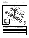
Sensing Module See sensing module checkout section. The sensing module is not field repairable and must be
replaced if found to be defective. See “Disassembly procedure” for instructions on disassembly.
Check for obvious defects, such as punctured isolating diaphragm or fill fluid loss, and contact
Rosemount Nuclear Instruments, Inc.
Power Supply Check the power supply output voltage at the transmitter.
Low Output or
No Output
Primary Element Check for restrictions at primary element, improper installation or poor condition. Note any changes
in process fluid properties.
Loop Wiring
Check for adequate voltage to the transmitter.
Check the milliamp rating of the power supply against the total current being drawn for all transmitters
being powered.
Check for shorts and multiple grounds.
Check for proper polarity at the signal terminal.
Check loop impedance.
Check wire insulation to detect possible shorts to ground.
Impulse Piping Ensure that the pressure connection is correct.
Check for leaks or blockage.
Check for entrapped gas in liquid lines.
Check for sediment in the transmitter process flange.
Ensure that blocking valves are fully open and that bypass valves are tightly closed.
Ensure that density of the fluid or other fluid properties in the impulse piping are unchanged.
Transmitter Electronics
Connections
Ensure that calibration adjustments are in allowable range.
Check for shorts in sensor leads.
Make sure post connectors are clean, and check the sensor connections.
If the electronics are still suspect, substitute new electronics.
Test Diode Failure Replace electronics housing.
Transmitter Electronics
Failure
Determine faulty circuit board by trying spare boards. Replace faulty circuit board.
Sensing Module See Sensing Module Checkout section. The sensing module is not field repairable and must be
replaced if found to be defective. See “Disassembly Procedure” for instructions on disassembly.
Check for obvious defects, such as punctured isolating diaphragm or fill fluid loss, and contact
Rosemount Nuclear Instruments, Inc.
Power Supply Check the power supply output voltage at transmitter.
Continued on Next Page
Do not use over 100 volts to check the loop, or
damage to the transmitter electronics may result.