


Reference Manual
00809-0100-4388, Rev BA
January 2008
5-5
Rosemount 1153 Series D
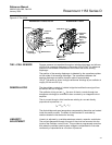
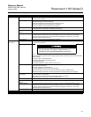
Preliminary 1. Replace the cover O-rings (2) whenever you remove a cover. Clean
the sealing areas with alcohol, if necessary, and lightly grease the
O-ring with Dow Corning 55 Silicone O-ring Grease (Rosemount P/N
01153-0248-0001 or P/N 01153-0053-0001). Spray the inside threads
of the electronics covers with cover lubricant (Rosemount P/N
01153-0333-0001 or equivalent) if necessary; if covers are already
sufficiently lubricated, do not spray.
2. Verify that the circuit boards are clean.
3. Verify that the bayonet pins on the connection board are clean.
4. If you remove the sensor module, clean the thread sealant from the
sensor module threads, lock nut, and electronics housing threads
with a wire brush.
Connecting Electrical
Housing to Sensor
Module
1. Run the lock nut down to the base of the sensor module threads.
2. Apply a heavy, continuous bead (about
3
/8-in. wide) of Loctite
®
580 PST sealant (RMT P/N 01153-0329-0001) around the top sensor
module threads.
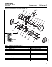
3. Insert the header assembly board (4) through the hole in the bottom
of the electronics housing.
4. Screw the sensor module (12) into the electrical housing (3) making
sure that five full threads are engaged. Be careful not to damage or
twist the sensor module leads. Turn the header board to avoid
twisting the wires.
5. Align the sensor module with the high and low pressure sides
oriented per Figure 2-5 on page 2-7, as applicable. Alternately,
tighten the module one-half turn further to reverse the orientation of
the module about the electronics housing.
6. Tighten the lock nut (9) to 35 ft-lb (48 N-m) torque.
7. Wipe off excess sealant.
8. Place the assembled unit in an oven at 200 ± 5 °F (93 ± 3 °C) for 12
hours to cure the sealant.
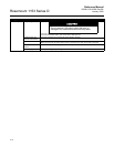
Electrical Housing
Reassembly
1. If zero and span adjustment screws (16) have been removed replace
O-rings with new O-rings (19). Lightly grease the O-rings with Dow
Corning 55 Silicone O-ring Grease (Rosemount P/N
01153-0248-0001 or P/N 01153-0053-0001). Reinstall the adjustment
screws and secure with snap rings (18).
2. Align the zero and span adjustment screws with the potentiometer
stems on the calibration board (5) and push the calibration board onto
the bayonet pins.
3. Slide the header assembly board (4) onto the bayonet pins with the
component side toward the pins. Slide any excess wire behind the
calibration board, taking care to avoid kinks.
4. Push the amplifier board (6) onto the bayonet pins and secure with
holding screws (7). Use nominal torque of 10 in-lb (1.1 N-m).
5. Carefully replace the cover and tighten to 16.5 ft-lb (22.4 N-m)
(“Preliminary” on page 5-5).
6. Replace the nameplate (17), and secure with two nameplate screws
(20).