


Reference Manual
00809-0100-4388, Rev BA
January 2008
3-3
Rosemount 1153 Series D
CALIBRATION
PROCEDURES
Zero and Span
Adjustment
NOTE
The Rosemount 1153 Series D Pressure Transmitter contains electronic
circuit boards which may be static sensitive.
NOTE
Covers need not be removed for zero and span adjustment.
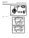
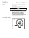
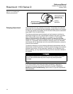
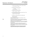
The zero and span adjustment screws are accessible externally. They are
located behind the nameplate on the side of the electronics housing (see
Figure 3-2 on page 3-3). The transmitter output increases with clockwise
rotation of the adjustment screws.
The zero adjustment screw has very little effect on the span. The span
adjustment, however, does affect the zero. The effect of interaction is more
apparent with suppression or elevation. The span adjustment changes the
zero output and the full-scale output by approximately the same percentage.
Therefore, it is best to calibrate the transmitter from zero to the desired span
and finish the calibration by adjusting the zero screw to achieve the desired
elevation or suppression.
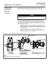
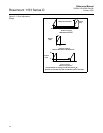
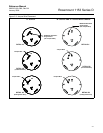
Figure 3-2. Zero and Span
Adjustment.
Example (for Range Code 4)
Initial Transmitter Calibration: 25 to 125 inH
2
O
(100 inH
2
O span with zero suppressed 25 inH
2
O).
Desired Transmitter Calibration: –75 to –25 inH
2
O
(50 inH
2
O span with zero elevated 75 inH
2
O).
Zero
Span