


Reference Manual
00809-0100-4388, Rev BA
January 2008
2-3
Rosemount 1153 Series D
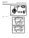
Proper location of the transmitter with respect to the process tubing depends
on various process parameters. When determining the best location, consider
the following:
• Keep hot or corrosive fluids from contacting the transmitter.
• Prevent sediment from depositing in the impulse tubing.
• Ambient temperature gradients and fluctuations can result in erroneous
transmitter readings.
• Keep impulse tubing as short as possible.
• For differential transmitters, balance the liquid head on both legs of the
impulse tubing.
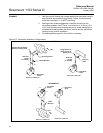
• For liquid flow or pressure measurements, make taps on the side of the
line to avoid sediment deposits, and mount the transmitter beside or
below the taps so gases vent into the process line (see Figure 2-6 on
page 2-8).
• For gas flow or pressure measurements, make taps on the top or side
of the line and mount the transmitter beside or above the taps so liquid
drains into the process line (see Figure 2-6 on page 2-8).
• For steam flow or pressure measurements, make taps on the side of
the line, and mount the transmitter below the taps so the impulse tubing
stays filled with condensate (See Figure 2-6 on page 2-8).
• For steam service, fill the lines with water to prevent steam from
contacting the transmitter. Condensate chambers are not necessary
since the volumetric displacement of the transmitter is negligible.
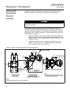
The piping between the process and the transmitter must transfer the
pressure measured at the process taps to the transmitter. Possible sources of
error in this pressure transfer are:
•Leaks.
• Friction loss (particularly if purging is used).
• Trapped gas in a liquid line or trapped liquid in a gas line (head error).
• Temperature-induced density variation between legs (head error), for
differential transmitters.
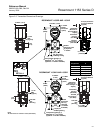
To minimize the possibility of errors, take the following precautions:
• Make impulse tubing as short as possible.
• Slope tubing at least one inch per foot up toward the process
connections for liquid and steam.
• Slope tubing at least one inch per foot down toward the process
connections for gas.
• Avoid high points in liquid lines and low points in gas lines.
• Use impulse tubing of sufficient diameter to avoid friction effects.
• Ensure that all gas is vented from liquid tubing legs.
• Ensure that impulse tubing is of adequate strength to be compatible
with anticipated pressures.