


3
1
PRE-OPERATION INSTRUCTIONS
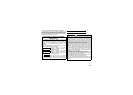
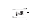
1.1.3 Parts
0
F
E
D
C
B
A
9
8
7
6
5
4
3
2
1
0
F
E
D
C
B
A
9
8
7
6
5
4
3
2
1
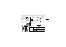
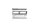
SW2
SW3
SW1
LED1
STATUS
X1X16
FR-A7NP
12
ON
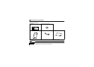
Front view Rear view
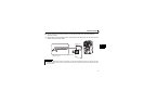
Mounting
hole
Mounting hole
Mounting hole
Mount on the
inverter with an
accessory mounting
screw.
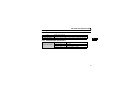
Terminal block
Connect
the communication
cable.
Connector
Connect to the inverter
option connector.
Terminal
layout
0
F
E
D
C
B
A
9
8
7
6
5
4
3
2
1
0
F
E
D
C
B
A
9
8
7
6
5
4
3
2
1
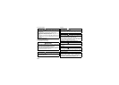
SW2
SW3
SW1
X1
X16
D+
D-
V-
D-
CNTR
FG
V+
D+
D-
D+
V-
FG
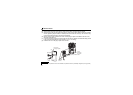
O
peration status indication
LED
Lit/off of the LED indicate
inverter
o
peration status.
Switch for manufacturer setting
Do not change from
initially-set status (1, 2:OFF).
Node address switch
12
ON
12
ON
(Refer to page 8, 10.)
(Refer to page 4.)
Name Function
Node address
switch
Set the inverter address within the range of 00H to
7DH.
Operation status
indication LED
OFF Inverter power OFF
Red is lit
A communication error with the master
occurred
Green is lit During communication with the master