


4
PRE-OPERATION INSTRUCTIONS
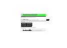
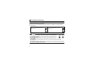
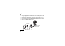
1.2 Node address setting
Set the node address between "00H to 7DH" using node address switches on FR-A7NP (refer to page 3).
The setting is applied at the next power-ON.
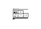
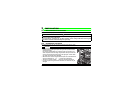
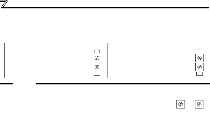
Set the arrow (×) of the corresponding switches to a number or an alphabet to set a desired address.
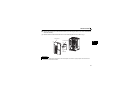
• Setting example
Node address 1:
Set the "
× " of X16(SW3) to "0" and the "× "
of X1(SW1) to "1".
Node address 38 (26H):
Set the " ×" of X16(SW3) to "2" and the "× "
of X1(SW1) to "6".
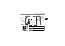
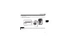
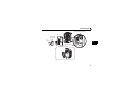
CAUTION
• Set the node address switch to the switch number (alphabet) position correctly. If the
switch is set between numbers, normal data communication cannot be established.
• Do not set the node addresses to 7EH through FFH. When these addresses are set,
they are recognized as 7DH.
• The node addresses, 00H, 01H, 02H, 7CH, and 7DH, may not be available for some
master modules.
• You cannot set the same node address to other devices on the network. (Doing so disables proper
communication.)
• Set the inverter node address before switching ON the inverter and do not change the setting while power is
ON. Otherwise you may get an electric shock.
X16
X1
0
1
2
3
4
5
6
7
8
9
A
B
C
D
E
F
0
1
2
3
4
5
6
7
8
9
A
B
C
D
E
F
X16
X1
0
1
2
3
4
5
6
7
8
9
A
B
C
D
E
F
0
1
2
3
4
5
6
7
8
9
A
B
C
D
E
F
Good
example
Bad
example
0
1
2
3
4
5
6
7
8
9
A
B
C
D
E
F
0
1
2
3
4
5
6
7
8
9
A
B
C
D
E
F