


32
INVERTER SETTING
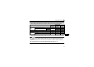
4.4.2 Fault and measures
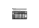
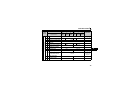
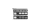
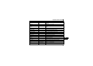
(1) The inverter operates as follows at fault occurrences.
* Depends on the Pr. 502 setting.
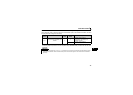
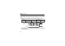
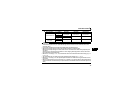
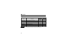
(2) Measures at error occurrences
When faults other than the above are displayed, refer to the inverter manual and remove the cause of the error.
Fault
Location
Status
Operation Mode
Network
Operation
External
Operation
PU Operation
Inverter
Inverter operation Inverter trip Inverter trip Inverter trip
Data communication Continued Continued Continued
Communication
line
Inverter operation Inverter trip * Continued Continued
Data communication Stop Stop Stop
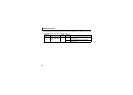
Communication
option
Communication
option
connection
error
Inverter
operation
Inverter trip * Inverter trip * Inverter trip *
Data
communication
Continued Continued Continued
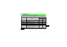
Error of
communication
option itself
Inverter
operation
Inverter trip * Continued Continued
Data
communication
Stop Stop Stop
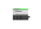
Fault Indication Error Definition Measures
E.OP1
Communication line
error
Check the LED status of the option unit and remove the cause of the
alarm. (Refer to page 3 for LED indication status)
Check the other nodes on the network.
Inspect the master.
E.1 Option fault
Check the connection between the inverter and option unit for poor
contact, etc. and remove the cause of the error.