


1–4 LM10 MOTOR PROTECTION SYSTEM – INSTRUCTION MANUAL
FEATURES CHAPTER 1: INTRODUCTION
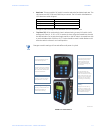
1.3 Features
1.3.1 Programming and Display Unit
The main task of the programming and display unit (PDU) is to provide status information
to a local user. The PDU can display the requested parameter(s) on the LCD in either English
or Spanish. Additionally, the PDU can be used to configure the LM10 via the RS232 serial
communications port.
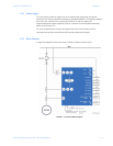
1.3.2 LED Indicators
The LM10 has five (5) LEDs on the front panel. They function as follows:
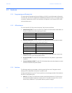
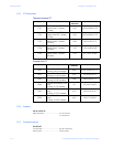
• Module Status (MS): This two-colored LED is used for the DeviceNet module status. Its
function is defined in the DeviceNet specification.
• Network status (NS): This two-colored LED is used for the DeviceNet network status.
Its function is defined in the DeviceNet specification.
• Overcurrent (OC): This red LED is illuminated when the relay detects an overcurrent
condition in one or more of the power phases.
• Ground Fault (GF): This red LED is illuminated when the relay detects a ground fault
condition.
• Current Unbalance (CUB): This red LED is illuminated when the relay detects a current
unbalance between the power phases.
1.3.3 Switches
The following switches are located on the front panel of the LM10. Changes to switch
settings will not take effect until power is cycled (on-off).
All other relay features (e.g., the CT sensor pack) can only be programmed via DeviceNet or
the RS232 configuration port.
• MAC ID: Two rotary DIP switches are used to set the DeviceNet MAC ID. Each unit on
the DeviceNet network requires a unique MAC ID. The valid ID range is from 0 to 63,
with a factory default of 0. Cycle power after any switch changes.
LED State Description
Off No power
Green Device operational
Red Unrecoverable fault
LED State Description
Off No power / not online
Flashing green Online, not connected
Green Link OK, online, connected
Flashing red Connection timeout
Red Critical link failure