


2–14 LM10 MOTOR PROTECTION SYSTEM – INSTRUCTION MANUAL
WIRING CHAPTER 2: INSTALLATION
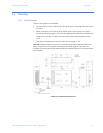
The LM10 base unit and PDU are designed to use a maximum 36-inch cable when the PDU
is mounted door-mounted alone. A shorter cable can be used when the two units are door-
mounted together.
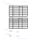
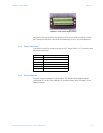
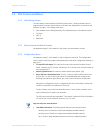
The connection for the RS232 serial communications port is shown in the following figure.
The EnerVista LM10 software can be used to configure and monitor the status of the LM10
through the RS232 port.
FIGURE 2–2: LM10 RS232 Pinout
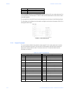
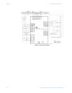
2.1.3 Control Terminals
The control terminal block is a phoenix contact style 0.2-inch center, dual-row, 16 points
per row removable connector. The connector will be used to make all field connections
(other than communications and CT sensors) to the unit. The terminal block has the
following connections:
5 +5 V (PDU use only)
6 N/A
RJ11 Pin Description
Table 2–1: Control Connections
Upper Signal Row Lower Signal Row
1 120 V AC - phase 1 17 Switch input - auxiliary 2
2 120 V AC - phase 2 18 Switch input - auxiliary 1
3 Switch input - stop 19 Switch input - run 2
4 Switch input - reset 20 Switch input - run 1
5 Switch input - common 21 Switch input - DeviceNet control
6 Relay 1 N.O. - run 22 Ground fault relay N.O.
7 Relay 1 common - run 23 Ground fault relay common
8 Chassis ground 24 Programmable relay N.O.
9 Relay 2 N.O. - run 25 Programmable relay N.C.
10 Ground fault relay N.C. 26 Programmable relay common
11 Relay 2 common - run 27 5 A CT 2 phase B
12 5 A CT 1 phase B 28 5 A CT 2 phase A
13 5 A CT 1 phase A 29 5 A CT 2 phase C
14 5 A CT 1 phase C 30 5 A CT 2 common
15 5 A CT 1 common 31 No connection
16 Ground CT 1 32 Ground CT 2