


A–8 LM10 MOTOR PROTECTION SYSTEM – INSTRUCTION MANUAL
LM10 AND GE FANUC 90-30 WITH DEVICENET™ CHAPTER A:
Z Enter a value of 7 bytes under input resource and 1 byte under
output resource.
This is the size of the slave status data and command data.
Z Make changes to the slave side settings.
Z Under the Ge n er a l tab, set the MAC ID equal to the MAC ID of the
slave device.
Z Select the Polled option under the Connection 1 tab.
The input and output byte size are defined and connection type is
Status and Control.
Z Place the PLC online and download the hardware and logic to the
PLC.
Z Observe the DeviceNet™ master module LEDs.
All three LEDs for NET POWER, MOD STATUS, and NET STATUS
should turn solid green.
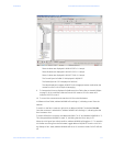
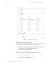
Z Open a new Reference View Table to monitor and control the
slave device, then add address %I00001 (Slave Status Bit Array).
Addresses %I00001 to %I00064 will display the status of all slave
devices connected to master card.
• For example, if the master card detects an LM10 slave device
with MAC ID 1, then address %I00002 will read “1”. Similarly, if a
slave is connected with MAC ID 2, then address %I00002 will read
“2”.
Z Start the PLC.
The NS LED on the LM10 (MAC ID 1) will turn solid green once the
connection is established, and address %I00001 will read “1”.
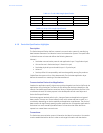
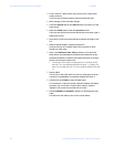
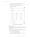
Z Double-click on GE LM10 to view the data areas.
For Connection 1 inputs (to master), address %I00081 will display
the status. For Connection 1 outputs (from master), address
%Q00017 will contain the command for the slave.
Z Add the %I00081 and %Q00017 registers to the Reference View
Table.
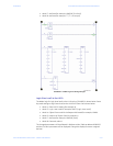
The reference view table for the LM10 is shown below.