


CHAPTER 1: INTRODUCTION FEATURES
LM10 MOTOR PROTECTION SYSTEM – INSTRUCTION MANUAL 1–5
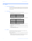
• Baud rate: This two-position DIP switch is used to select the DeviceNet baud rate. The
valid rates are 125K, 250K and 500K bits per second. The DIP switch is defaulted to
125K baud rate when shipped.
Changes to switch settings will not take effect until the next power cycle.
• Trip Class (TC): NEMA overload trip class is selected using a rotary DIP switch. Valid
settings are Class 10, 15, 20, or 30. To set the trip class, align the screwdriver slot with
the desired value. Do not use the triangle marker on the DIP switch. A screwdriver with
a nominal blade width of 0.094 to 0.175 inches should be used. Smaller blades could
allow the switch to be set in an invalid position.
Changes to switch settings will not take effect until power is cycled.
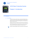
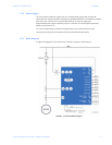
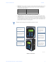
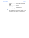
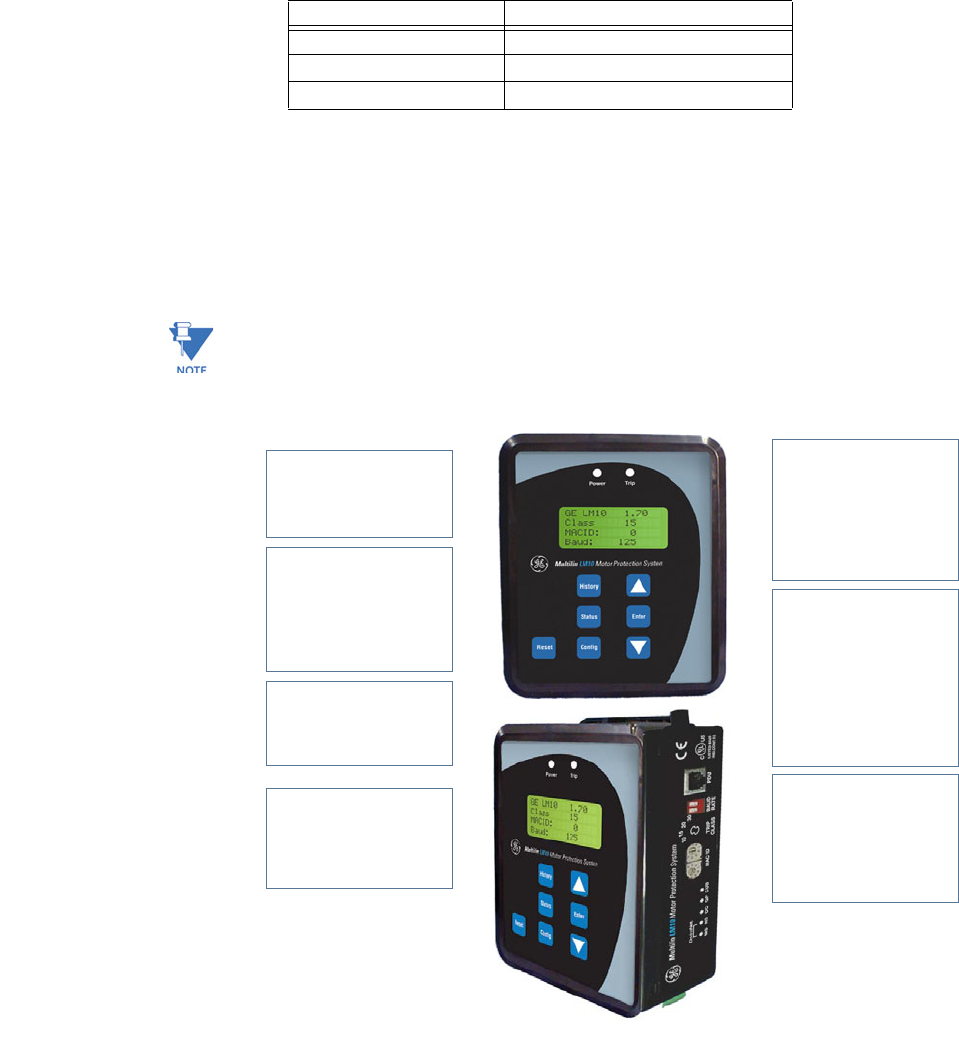
FIGURE 1–2: LM10 Features
Baud Rate DIP Switch Position
125 kbps down - down
250 kbps up - down
500 kbps up - up
849713A3.CDR
Display
Liquid crystal display: fourlines
of 16 characters perline.
Status
The status sub-menu candisplay
current, motor status, Run1 and
Run 2 data, faults,MAC ID, baud
rate, and overload class.
Reset
The relay canbe reset from the
PDU, pushbutton, orthe LAN.
Mounting Flexibility
The relay canbe attached to the
PDU without hardware to
facilitate door mounting.
LEDS
One green LEDpower indicator
and a flashing red trip LEDto
indicate over/undercurrent,
current unbalance, ground
fault, under/overvoltage, and
trip command.
CONFIG
The relay parametersare
programmed via theCONFIG
button. The CONFIG sub-menu is
similar to the statusmenu, and
allows the user tochange relay
parameters: CT ratio, PT ratio,
fault settings, and timedelays.
History
Displays the last ten(10) trip
records. Theconditions at the
time of fault are displayed and
can be scrolled through using
the UP/DOWN arrow keys.