


CHAPTER A: LM10 AND ALLEN-BRADLEY SLC500 VIA DEVICENET™
LM10 MOTOR PROTECTION SYSTEM – INSTRUCTION MANUAL A–17
A.3 LM10 and Allen-Bradley SLC500 via DeviceNet™
A.3.1 Description
This section describes DeviceNet communications between the Allen-Bradley SLC500 PLC
card with the GE Multilin LM10 Motor Protection System.
The application example shows how to establish communications between Allen-Bradley
SLC500 PLC (1747-SDN DeviceNet Scanner) card with the LM10 via Polled I/O Messaging,
COS I/O Messaging, and Explicit Messaging.
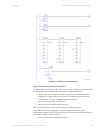
A.3.2 System Setup
The hardware for the setup example is indicated below:
• PLC: Allen-Bradley SLC500
• CPU: 5/03
• Power Supply: 1746-P1
• DeviceNet Scanner Card: 1747-SDN
• 4 Slot Rack: 1746-A4
• Interface Adapter DeviceNet to RS232: 1770-KFD
• The following Rockwell automation software is used:
•RSLogix 500
• RSNetworx for DeviceNet
•RSLinx
• The following settings are stored in the LM10:
•MAC ID: 09
• Baud Rate: 125
• Pin 21 (control input) connected to 110 V
A.3.3 Initial Steps
Before setting up the DeviceNet network, perform the following steps.
Z Start the RSLinx, RSNetworx, and RSLogix software and load the
corresponding drivers in RSLinx.
Z Establish Polled I/O, COS I/O, and Explicit Messaging between the
slave LM10 relay and the DeviceNet scanner card 1747-SDN.
The Polled I/O messaging is for control and monitoring. The COS I/O messaging is for
monitoring only. Explicit Messaging is used to retrieve byte wide data (for example, motor
run time in hours, line voltage).
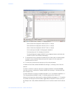
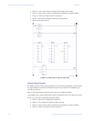
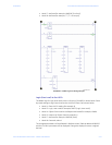
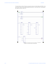
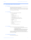
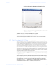
A.3.4 Setting Up the DeviceNet Network
Set up the DeviceNet network as follows: