


A–22 LM10 MOTOR PROTECTION SYSTEM – INSTRUCTION MANUAL
LM10 AND ALLEN-BRADLEY SLC500 VIA DEVICENET™ CHAPTER A:
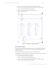
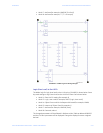
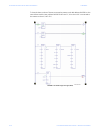
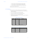
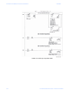
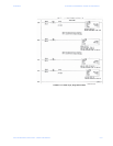
A.3.9 Data Table Layout
The data table layout is shown below.
Note that X will be any number set in the data file.
The TXID high byte is used for message tracking and is incremented and checked by ladder
logic. The Command low byte is defined as follows:
• 1 = Execute the block
• 2 = Clear response buffer (1747-SDN only)
• The Port high byte is defined as follows:
• 0 = Channel A
• 1 = Channel B
The Port byte is always “0” for the 1747-SDN.
The Size low byte represents the number of bytes in the transaction body. Essentially, this
is the number of bytes following the MAC ID field.
The Service high byte is defined as follows:
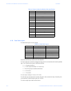
Table A–3: Status Codes Provided by ODVA Specification
Status Data Definition
0 Transaction Block Empty
1 Transaction successful
2 Transaction in progress
3 Slave not in scan list
4 Slave offline
5 DeviceNet port disabled
6 Transaction TXID unknown
7 Unused
8 Invalid command
9 Scanner out of buffers
10 Other transaction in progress
11 Could not connect to slave device
12 Response data too large for block
13 Invalid port
14 Invalid size specified
15 Connection bust
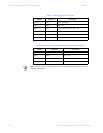
Table A–4: Data Table Layout
Data Location High Byte Low Byte
N X:0 TXID Command
N X:1 Port Size
N X:2 Service MAC ID
N X:3 Class (high byte) Class (low byte)
N X:4 Instance (high byte) Instance (low byte)
N X:5 Attribute (high byte) Attribute (low byte)
N X:6 Data (high byte) Data (low byte)