


CHAPTER A: LM10 AND ALLEN-BRADLEY SLC500 VIA DEVICENET™
LM10 MOTOR PROTECTION SYSTEM – INSTRUCTION MANUAL A–19
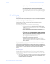
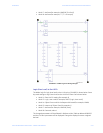
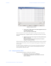
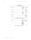
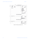
FIGURE A–6: Sample Force File
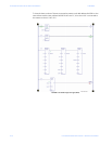
Z To place the 1747-SDN scanner in Run Mode, toggle the bit O:1/0 to
1 in the O0-output force file.
The CPU will change to the Run state.
When the scanner is in Run mode and the network is healthy, the node number of the
scanner is displayed on the 7-segment indicator on the module. In this case, “63” will be
displayed.
Z Toggle the O:1/0 to 0 in the O0-output force file to place/force the
Scanner to Idle mode.
The scanner will also change to Idle mode when CPU mode is
changed to Prog (programming).
When the scanner is in Idle mode, the 7-segment indicator will flash code “80” and the NS
(Network Status) LED indicator on the LM10 changes to flashing green, indicating Online,
Not Connected.
If the Run1 contactor is switched on via O:1/16, then Run1 will drop/turn off when the
scanner changes to Idle mode. The Run1 contactor will pickup again (ON) when the
scanner goes from Idle to Run mode.
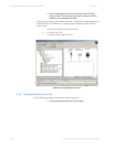
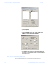
A.3.6 Configuring the Slave Device
Use the following procedure to configure the slave device.
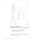
Z Double-click on the scanner icon in RSNetworx.
This will display a configuration screen related to 1747-SDN
scanner (see below).