


CHAPTER 4: FUNCTIONALITY CONFIGURATION SETTINGS
LM10 MOTOR PROTECTION SYSTEM – INSTRUCTION MANUAL 4–33
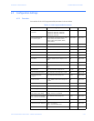
• FLA (full load current) The LM10 Motor Protection System is designed to work in
conjunction with a spectrum of motor starters. Therefore it handles full load currents
ranging from 1.2 to 800 amps. The correct FLA for the motor in use must be
programmed for relay protection to function properly.
Enter the full load current (FLA) of the motor. The LM10 will not accept full load currents that
exceed the CT or sensor pack rating; however, lower values are acceptable. For best results,
enter the proper FLA for the motor being used. Refer to Overcurrent Fault Conditions on
page 4–25 for additional details.
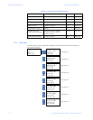
• Ground Setup: A zero-sequencing ground fault can be enabled to trip and operate a
separate ground fault relay when ground fault current exceeds the Ground Setup
Fault setpoint. The Ground Setup Time Delay setting is from 0.5 to 2.5 seconds.
Ground current can be continuously monitored at the PDU or over the network.
A ground fault CT or sensor shall be connected for this protection.
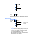
• JAM Setup: According to NEMA or IEC MG 1-1998 part 12, page 21, “polyphase motors
600 V or less not exceeding 500 hp shall be capable of withstanding a current not less
than 1.5 times the full load rated current for not less than two minutes when the
motor is at normal operating temperature.” For relatively low overcurrent conditions,
particularly on higher NEMA class motors, trip times could be considerably longer than
2 minutes. Therefore, a separate jam fault is available as the standard time
overcurrent curve may not protect in this range.
The user may set a JAM Setup Fault level of 100 to 250% of FLA or disable this function.
The default setting is set to disabled.
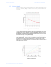
The overcurrent curve cannot be disabled. Therefore, if the
JAM Setup Time Delay is set
greater than the time allowed by the standard trip curve, the LM10 will trip before a Jam
condition can be reached. See Trip Curve with Jam and Stall Enabled on page 4–27 for an
example of the effect of trip times.
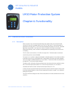
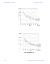
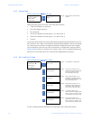
• STALL Setup: Cold motor trip times for a 6 × FLA fault are determined by trip class. For
example, a NEMA class 20 motor at 6 × FLA would trip in 20 seconds. A separate Stall
fault is available which would allow the user to reduce the trip time for large
overcurrent situations.
The user may set a STALL Setup Fault level of 330 to 600% of FLA or disable this function.
The default setting is disabled.
The overcurrent curve cannot be disabled. Therefore, if the STALL Setup Time Delay is set
greater than the time allowed by the standard trip curve, the LM10 will trip before a stall
condition can be reached. See Trip Curve with Jam and Stall Enabled on page 4–27 for an
example of the effect of trip times.
• CurUnB Setup (current unbalance setup): The LM10 monitors the three current phases
and trips if the phases are unbalanced. In addition to phase A, B, and C current, this
function takes FLA, CT ratio and number of passes/turns through the CT into account.
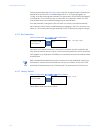
If the average current exceeds FLA, then this average value is used in the formula
instead of the FLA value. The formula is:
(EQ 4.1)
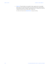
The next formula uses the largest Δ of the three phases.
(EQ 4.2)
The default
CurUnB Setup Fault value is “Disabled” since not every application will require
current unbalance monitoring. The current unbalance is programmable between 2 to 25%
of FLA.
Δ phase current average current–=
unbalance level Δ FLA⁄()100%×=