


A–6 LM10 MOTOR PROTECTION SYSTEM – INSTRUCTION MANUAL
LM10 AND GE FANUC 90-30 WITH DEVICENET™ CHAPTER A:
A.2 LM10 and GE Fanuc 90-30 with DeviceNet™
A.2.1 Overview
This section describes an example communications setup between the LM10 Motor
Protection System and the GE Fanuc 90-30 PLC via the DeviceNet protocol.
• Explicit Messaging: for configuration and monitoring.
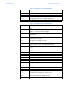
• All the values mentioned in DeviceNet™ object model (voltage, current, power
factor, trip class, FLA settings, etc.) can be monitored.
• Polling Input/Output Connection: commands to the slave device and status from
the slave device.
• Data for assemblies #5 and #54. With polling, the Run1 and Run 2 contactors can
be controlled. Note that only one relay output can be energized a time.
• COS (Change of State) and Cyclic Input/Output Connection: for alarm/event
notifications
Essentially, the COS/Cyclic connection is intended for monitoring the status of the Run1
and Run2 contactors.
A.2.2 GE Fanuc 90-30 PLC Hardware
The hardware for the setup example is indicated below:
• Main Rack (Base 10 Slot or Base 5 Slot IC693CHS391/7)
• Power Supply (IC693PWR XXX)
• CPU (IC693CPU XXX) except CPU321 & CPU340
• DeviceNet Master Module (IC693DNM200)
• GE Fanuc Software: Cimpilcity ME version 4.00
• DeviceNet Slave Module: GE Multilin LM10 Motor Protection System
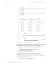
A.2.3 Network Configuration
To connect the LM10 Motor Protection System to the DeviceNet™ master card
(IC693DNM200), refer to chapter 2 of the Series 90-30 Programmable Controller manual
(publication number GFK-2196).
A.2.4 Configuration Procedure
Z Complete the basic setup of the rack, power supply, and CPU.
Z Add the DeviceNet™ master card (IC693DNM200) to any non-CPU
slots 2 to 10.
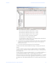
Z Start the GE Fanuc Cimpilcity ME software.
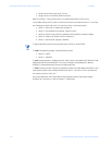
Z Add the slave device by right-clicking on the slot containing the
DeviceNet™ master card, then click Add Slave.
A slave catalog will be displayed.