


CHAPTER A: LM10 AND ALLEN-BRADLEY SLC500 VIA DEVICENET™
LM10 MOTOR PROTECTION SYSTEM – INSTRUCTION MANUAL A–23
• 0E (hex), 14 (decimal) = Get Attribute Single (read a single parameter)
• 10 (hex), 16 (decimal) = Set Attribute Single (write a single parameter)
• 32 (hex), 50 (decimal) = Get Attribute Multiple (read multiple parameters)
The MAC ID low byte is destination code 09.
The transaction body consists of the Class, Instance, Attribute, and Data bytes.
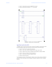
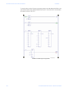
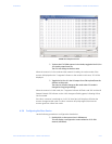
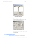
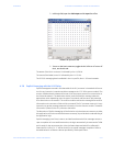
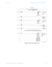
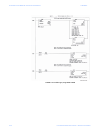
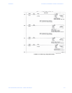
A.3.10 Ladder Logic
This discussion refers to the Ladder Logic diagrams shown on the following pages.
1. Rung 0000 to Rung 0004 are used to toggle the Bit B4/0 every 1 second; this is the
input to BSL (Bit Shift Left).
2. For every 1 second toggle of B4/0, left-shift the N9:0 register.
3. The bits in the N9:0 register are used to enable Rungs 0007 to 0012.
4. Rung 0006 is used to reload the N9:0 register after overflow.
5. The COP function is used to copy the contains of the M1 file to a specific N register and
transfer the values to the M0 file.
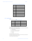
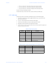
Table A–5: Data to Get Trip Class
Address Data (hex) Description
N31:0 0101 TXID / Command
N31:1 0008 Port / Size
N31:2 0E09 Service / MAC ID (Node 09)
N31:3 0064 Class
N31:4 0001 Instance
N31:5 002F Attribute (Trip Class)
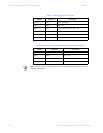
Table A–6: Data for Explicit Message Response, M1 Transferred to N20
Address Data (hex) Description
N32:0 0101 TXID / Command
N32:1 0002 Port / Size
N32:2 8E09 Service / MAC ID (Node = 09)
N32:3 Trip Class Value Service Response Data