


5–62 LM10 MOTOR PROTECTION SYSTEM – INSTRUCTION MANUAL
DEVICENET OPERATIONS CHAPTER 5: COMMUNICATIONS
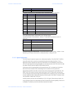
This data was initially setup for development purposes. An explicit message through the
custom class 100(0x64) is the only way to access this data. The DeviceNet message to read
this data is: service 0x0e, class 0x64, instance 1, and attribute 0x34. The response will be a
16-bit word with MACID switches in the high byte and AC switch input bits in the low byte.
• Sent by scanner: CANID, MACID, 0x0E, 0x64, 0x01, 0x34
• Response from the LM10: CANID, MACID, 0x8E, LBY, HBY
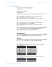
The format of this data follows F25: Input Switch Status. The high byte (HBY) is not used in
this application. The low byte (LBY) is the input data we are looking for. The seven hard
wired inputs map to bits 0 to 6 as DeviceNet Control, AxSn2, AxSn1, RUN2, RUN1, Reset,
Stop. To watch for RUN1 one would test for bit 2 being on. EX: LBY and 0x04 is not equal to
0x00.
Do not switch out of DeviceNet Control while the motor is running. In such a case the LM10
will issue a Stop command under the assumption that the network is down.