


CHAPTER A: LM10 AND GE FANUC 90-30 WITH DEVICENET™
LM10 MOTOR PROTECTION SYSTEM – INSTRUCTION MANUAL A–9
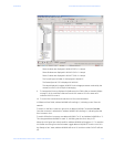
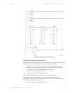
Phase A values are displayed in %I00105 (223 × 0.1 amps).
Phase B values are displayed in %I00121 (212 × 0.1 amps).
Phase C values are displayed in %I00137 (218 × 0.1 amps).
The Control Byte via Polled I/O is displayed in %Q00017.
The Status Byte via COS is displayed in %I00145.
The value displayed in register %R0256 is the voltage parameter received by the
master from the LM10 via Explicit Messaging.
9. To interpret the bit array displayed in Reference View Table, refer to Assembly Object
on page 5–48, in particular instances 54 and 100. Instance 54 is for status and
Instance 100 is for control.
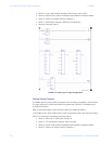
10. To control the contactors and reset the LM10 from the fault state:
In Reference View Table, address %I00086 will read logic 1, indicating control from the
network.
To switch on the Run1 contactor, right-click on address %Q00017 and select Turn On.
Once the contactor is switched on, address %I00083 will read logic 1, indicating that the
Run1 contactor is on.
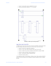
To switch off the Run1 contactor, set address %Q00017 to “0” and address %Q00020 to “1”.
This changes address %I00083 to read “0”, indicating that the Run1 relay is off.
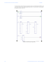
When the LM10 goes into a fault condition, address %I00081 will toggle to “1”. To reset the
LM10 after recovering from the fault state, toggle address %Q00019. Once the LM10 is in
the “Ready to Run” state, address %I00081 will set to “0” and the module CUB LED will turn
off.