


CHAPTER 2: INSTALLATION WIRING
LM10 MOTOR PROTECTION SYSTEM – INSTRUCTION MANUAL 2–15
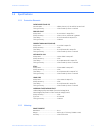
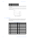
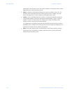
FIGURE 2–3: LM10 Control Signal Contacts
Service hint: Remove the bottom terminal block first, using a small screwdriver in either
end. The top terminal block can then be removed using a coin or any broad-blade tool.
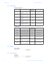
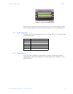
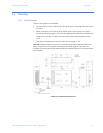
2.1.4 Sensor Pack Input
Connectors S1 and S2 are used to connect to all CT Sensor Packs. 5 A CTs connect via the
Phoenix terminal block.
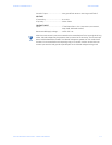
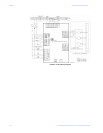
2.1.5 Wiring Diagram
A typical LM10 wiring diagram is shown below. The relay should be programmed as
“Maintained Off” (under “Other Settings”) for momentary start input. See page 4–34 for
additional details.
S1/S2 Pins Description
1CT phase A
2CT phase B
3CT phase C
4 CT phase A common
5CT phase B common
6CT phase C common