


5–50 LM10 MOTOR PROTECTION SYSTEM – INSTRUCTION MANUAL
DEVICENET OPERATIONS CHAPTER 5: COMMUNICATIONS
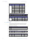
Assembly Object, Class Code 4, Instance 54. Use this object for data received by the master
from the slave device.
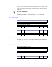
Assembly Object, Class Code 4, Instance 100. Use this object for data transmitted from the
master to the slave device.
* If the LM10 has been put into Admin mode via the PDU display and this bit is set to '1', the
PDU display will continue to appear to be in Config mode but no settings will be able to be
changed. The LM10 will now be in 'User' mode.
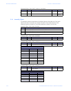
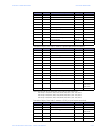
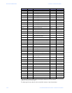
Assembly Object, Class Code 4, Instance 101:
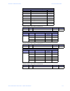
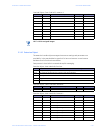
Bit 4 Reserved ---
Bit 3 Reserved ---
Bit 2 Running 1 ---
Bit 1 Warning ---
Bit 0 Fault ---
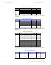
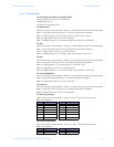
Attribute Access Name/Description Data Type Value
3 Get Device inputs (see format/mapping below) byte see below
Data Formats for Device Inputs
Bit Position Name Value
Bit 7 Aux Sense 2 unput status ---
Bit 6 Aux Sense 1 unput status ---
Bit 5 Control from Devicenet ---
Bit 4 Reserved ---
Bit 3 Running 2 ---
Bit 2 Running 1 ---
Bit 1 Reserved ---
Bit 0 Fault ---
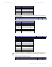
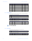
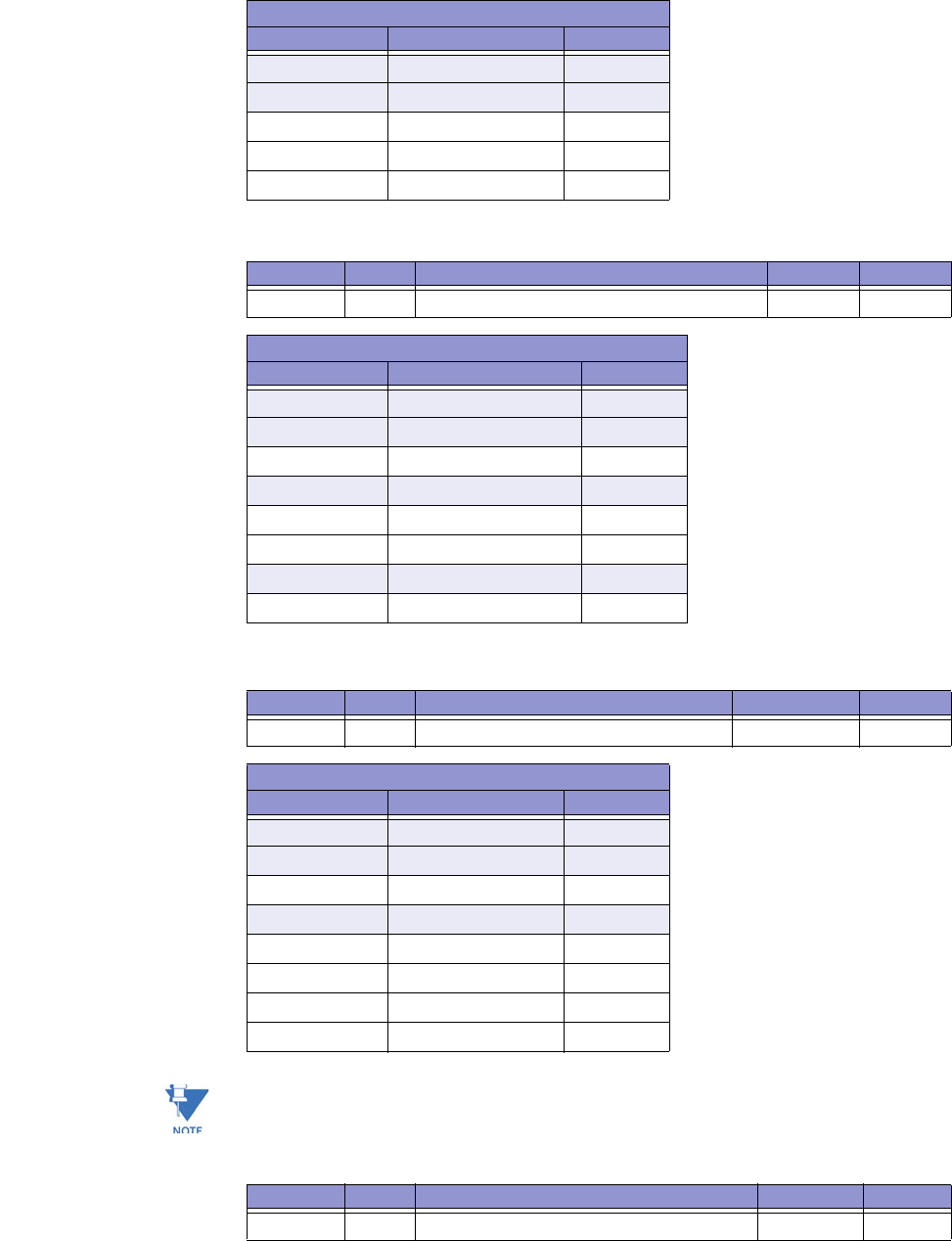
Attribute Access Name/Description Data Type Value
3 Set Control (see format below) byte see below
Data Formats for Device Inputs
Bit Position Name Value
Bit 7 Reserved ---
Bit 6 Reserved ---
Bit 5 Security to Min* ---
Bit 4 Reserved ---
Bit 3 Stop ---
Bit 2 Fault Reset ---
Bit 1 Run 2 ---
Bit 0 Run 1 ---
Data Formats for Device Inputs
Bit Position Name Value
Attribute Access Name/Description Data Type Value
3 Get Fault and status (see format below) byte see below