


CHAPTER A: DEVICENET OVERVIEW
LM10 MOTOR PROTECTION SYSTEM – INSTRUCTION MANUAL A–3
A.1.4 Explicit Messaging and Input/Output (I/O) Messaging
Explicit messages contain information such as vendors, parameters, etc. of a device. This
information is comparatively less important than the I/O message; as such, it is sent with a
higher CAN identifier as not to disturb the exchange of I/O messages on the bus.
Input/Output (I/O) messages contain the real-time I/O information of a device. In order to
achieve “real time”, these messages are sent as quick as possible; therefore, they are sent
with a lower CAN identifier than explicit messages.
A.1.5 Pre-defined Master/Slave Connection Set
A set of connection identifiers known as the Pre-defined Master/Slave Connection Set has
been specified to simplify the movement of I/O configuration-type data typically seen in a
master/slave architecture. An important benefit is that the establishment of connections
from the pre-defined set is simplified considerably. Only a few messages are required to
have I/O connections up and running. The pre-defined set contains one explicit messaging
connection and allows several different I/O connections including:
• bit strobed command/response
• polled command/response
• change of state
•cyclic
A.1.6 DeviceNet Features
DeviceNet's features include:
1. Low cost.
2. High speed. DeviceNet supports 3 baud rates: 125 kbps, 250 kbps, and 500 kbps. This
meets 95% of typical industrial requirements.
3. Reliability. DeviceNet uses the well proven CAN protocol with application layers that
have undergone strict conformance testing to ensure reliability.
4. Support of up to 64 active nodes.
5. Easy installation.
6. Removal and replacement of devices from the network under power.
7. 0 to 8 byte data packets.
8. Linear (trunk line/drop line) bus topology, with power and signal on the same network
cable.
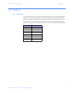
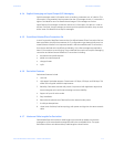
A.1.7 Maximum Cable Lengths for DeviceNet
DeviceNet defines the maximum cable lengths (trunk and drop cables) to ensure the
propagation of the transmitted message falls within the acceptable limits. The upper
boundaries of the trunk cable and drop cable length are shown below.