


CHAPTER 5: COMMUNICATIONS DEVICENET OPERATIONS
LM10 MOTOR PROTECTION SYSTEM – INSTRUCTION MANUAL 5–61
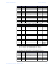
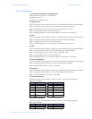
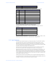
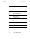
The third 4-bit section is an enumeration which indicates the cause of the fault.
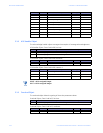
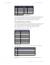
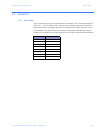
F25: Input Switch Status (16-bit value; use only lower byte)
Format: two bytes in format 0xHHLL, where LL is the Switch Input status and HH is
Reserved.
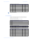
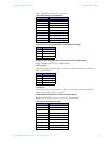
F26: Remaining Cool-Down Period - Format: two bytes in format 0xHHLL, where LL is the
Remaining Cool-Down Period and HH is Reserved. Byte LL Range: 0 to 99
5.1.12 Special Application
The LM10 Motor Protection System has a DeviceNet interface. The DEVICENET CONTROL
input will set the RUN control to be operated using the DeviceNet interface. For this
application we will assume this input to be tied active. This will disable any hard-wired
120 V AC RUN inputs from being accepted as a command to the LM10. The LM10 can read
the state of these inputs through the DeviceNet protocol.
With the use of this read request the DeviceNet scanner (PLC or Master) can check the
state of the local switches. After evaluating that all conditions of the system are
appropriate the RUN command can be sent to the LM10 through the DeviceNet link. The
RESET and STOP inputs do remain active at all times. The STOP input will command the
LM10 to stop the motor even though the DeviceNet is the controlling input. The DeviceNet
scanner would be able to detect this stop by monitoring the LM10 status. The status word
can be polled or setup as a Cos/Cyclic.
Auxiliary sense inputs are also activated by a 120 V AC signal. If the end user desires, he
may use these inputs for an alternate purpose if the Auxiliary Sense capability of the LM10
is disabled. The data is part of the same word as the RUN inputs.
1--- ---- ---- ---- Motor hot at time of fault
Value Bitmask Status
0 ---- 0000 ---- ---- None
1 ---- 0001 ---- ---- Overcurrent
2 ---- 0010 ---- ---- Ground fault
3 ---- 0011 ---- ---- Jam lock
4 ---- 0100 ---- ---- Stall aux
5 ---- 0101 ---- ---- Current unbalance
6 ---- 0110---- ---- Aux sense
7 ---- 0111 ---- ---- Load loss
8 ---- 1000 ---- ---- Reserved
9 ---- 1001 ---- ---- Reserved
10 ---- 1010 ---- ---- DeviceNet
11 ---- 1011 ---- ---- Operating voltage
Bitmask (LL) Status
---- ---1 Stop switch input switch
---- --1- Reset switch input switch
---- -1-- Run1 switch input switch
---- 1--- Run2 switch input switch
---1 ---- Auxsense1 switch input switch
--1- ---- Auxsense2 switch input switch
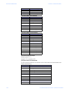
Bitmask Status