


CHAPTER 5: COMMUNICATIONS DEVICENET OPERATIONS
LM10 MOTOR PROTECTION SYSTEM – INSTRUCTION MANUAL 5–51
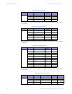
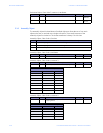
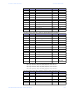
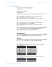
Assembly Object, Class Code 4, Instance 102
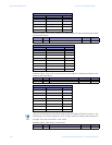
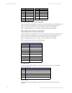
Assembly Object, Class Code 4, Instance 103
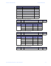
Assembly Object, Class Code 4, Instance 104
Data Formats for Device Inputs
Bit Position Name Value
Bit 7 DeviceNet Stop Issued Last ---
Bit 6 Reserved ---
Bit 5 DeviceNet Control ---
Bit 4 Reserved ---
Bit 3 Running 2 ---
Bit 2 Running 1 ---
Bit 1 Reserved ---
Bit 0 Fault ---
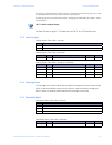
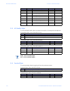
Attribute Access Name/Description Data Type Value
3 Get Poll Data Group 1 see below see below
Data Formats for Device Inputs
Bytes Data Length Name/Description Data
Format
Value
7 bytes 1 byte Motor status F21 ---
1 word Phase A current UINT × 0.1 A
1 word Phase B current UINT × 0.1 A
1 word Phase C current UINT × 0.1 A
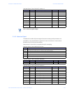
Attribute Access Name/Description Data Type Value
3 Get Poll Data Group 2 see below see below
Data Formats for Device Inputs
Bytes Data Length Name/Description Data
Format
Value
12 bytes 1 word Motor status F22 ---
1 word Cause of trip F20 ---
1 word Average phase current UINT × 0.1 A
1 word Ground current UINT × 0.1 A
1 word Current unbalance UINT %
1 word Power UINT × 0.1 kW
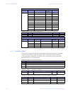
Attribute Access Name/Description Data Type Value
3 Get Poll Data Group 3 see below see below