


CHAPTER A: LM10 AND GE FANUC 90-30 WITH DEVICENET™
LM10 MOTOR PROTECTION SYSTEM – INSTRUCTION MANUAL A–11
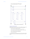
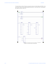
Z Double-click the added slave device to view the data area for
Connection 2.
Z Open the Reference View Table and add address %I00089.
Z To interpret the 1 byte of status information for address %I00097,
refer to Object Class 4, Instance 54 in Assembly Object on page 5–
48.
A.2.8 Explicit Messaging
Description:
Explicit messaging provides multi-purpose, point-to-point communication paths between
two devices. It typically provides request/response-oriented network communication used
to perform node configuration and problem diagnosis.
In the GE Multilin LM10 Motor Protection System. explicit messaging is used for
configuration and monitoring.
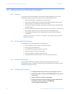
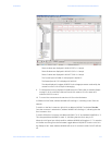
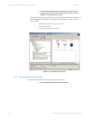
Use the following procedure to set the network for explicit messaging:
Z For the master side: In the Network Setting > DN9030 Master
Properties menu, disable connections 1 and 2 by selecting Enable
Explicit Connection.
Z Set the Message Request Size and Message Response Size to 20
bytes.
Z For the slave side: In the Network Setting > Disable Connection 1
& 2 window, select Explicit Message Size set the value as 20 bytes.
Z Connect the PLC and download the hardware logic.
The configuration should be shown as = EQ.
Z Observe the DeviceNet master module LEDs.
All three LEDs for NET POWER, MOD STATUS, and NET STATUS
should turn solid green. Refer to LEDs on page 3–19 to interpret the
device LED status.
Explicit messaging between the DeviceNet master module and LM10 slave takes place
using COMMREQ ladder instructions.
A communication request begins when a COMMREQ ladder instruction is activated in the
PLC application program. The CPU sends the COMMREQ to the DeviceNet™ master module
in the PLC system. The module receives the command and performs the requested
function.
Monitoring Data:
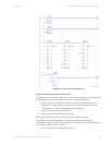
The ladder logic for monitoring data from the GE LM10 Motor Protection System using
COMMREQ is shown in Ladder Logic for Data Monitoring on page A–13. The ladder logic is
configured as follows:
• Rung 1 and 2 have a timer (thousands), as well as set and reset coils, which toggle
the T1 contact after the timer PV value overflows. With the values shown, the T1
contact will toggle every five (5) seconds.