


4–42 LM10 MOTOR PROTECTION SYSTEM – INSTRUCTION MANUAL
MOTOR START/STOP LOGIC CHAPTER 4: FUNCTIONALITY
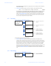
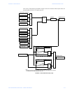
4.5 Motor Start/Stop Logic
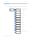
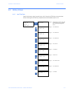
LM10 is designed to run in RUN1 and RUN2 mode. However, to illustrate this, only RUN1
mode is described below. The block logic diagram for RUN1 operation is shown in fig. 4-5.
Motor Status: Running 1
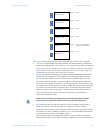
The relay can receive the RUN1 Start command as follows:
1. Start command through hardware RUN1 switch input
2. The RUN1 command is selected from the PDU in the configuration mode (used
for Test only)
3. Autorestart: the LM10 automatically returns to RUN1 operation after a power
loss of up to 4 seconds provided the autorestart setpoint has been enabled
and motor was running in RUN1 mode before the power loss
4. A start command is issued remotely through DeviceNet.
A PDU logged-in for configuration will disable run commands from both DeviceNet and
hardwired switches.
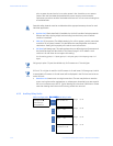
Motor Stop
Once the motor is in RUN1, it can be stopped as follows:
1. User asserts a hardware STOP switch Input
2. User de-asserts the RUN1 Hardware switch input (Maintained switch setting
set to ON)
3. A STOP command issued through a PDU Running Operations command (When
RUN1 command issued from PDU)
4. A stop command issued through DeviceNet
5. The relay trips on a protection function operation
6. RUN2 start command issue
7. The relay changed from USER mode to CONFIGURATION mode.
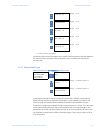
AUX Sense 1 Fault
Aux. Sense 1 fault for open contactor is detected if the main contactor status is still open
after 0.1 to 25.0 seconds (user settable) of the RUN1 O/P signal has been issued. The
contactor status is fed back to the relay through the AUX. Sense switch Input.