


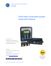


1–2 LM10 MOTOR PROTECTION SYSTEM – INSTRUCTION MANUAL
OVERVIEW CHAPTER 1: INTRODUCTION
1.2 Overview
1.2.1 Features
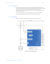
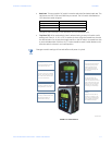
The LM10 Motor Protection System is a microprocessor-based unit. It takes a ‘snapshot’
image of the three phases of current, one phase of voltage, and ground. The data is then
applied to the algorithms and compared to the device's configuration information. Based
on the result of the comparison, the relay may trip one or more of the on-board control
relays. When applicable, indicators will be illuminated to show the status of the device.
Additionally, up to ten trip events will be stored in non-volatile memory.
The LM10 auxiliary communications port to the PDU is an RS232 interface using a
standard four-pin RJ11 style cable. This port will allow the PDU to obtain and display any of
the real-world data that is contained in the relay as well as to configure the relay.
The LM10 Motor Protection System supports the DeviceNet protocol and can be interfaced
with the PLC DeviceNet mastercard or DCS Scanner card. It supports Polled, Change of
State (COS), Cyclic I/O Messaging, and Explicit Messaging.
1.2.2 Current and Voltage Inputs
The relay has inputs for two sets of three-phase current transformers (CTs) and one ground
CT. One set will allow for custom 27 A and 90 A CT sensor packs to be connected; the other
will allow for 75 to 800:5 A ratio CTs. Dual speed motors will require two separate CTs
connected in parallel.
A 100:1 A core-balance CT or 20 A ground fault sensor pack can be connected to the
ground CT terminals for ground current measurement.
Provisions have been made to support various CTs for the three-phase measurements.
Voltage input from the control power transformer (CPT) is conditioned and measured by
the analog-to-digital converter to determine supply voltage. This signal, in conjunction
with the current, is used to calculate power and power factor.
1.2.3 Relay Outputs
The LM10 Motor Protection System contains 4 on-board Form-C relays with NEMA C150
pilot duty ratings. Two relays should be used to control the coils of motor contactor and
one to annunciate ground fault status. An additional programmable relay is available for
fault status indications.
The two control relays are labeled “RUN 1” and “RUN 2”. These relays are enabled on
command from the control logic. If the LM10 detects a fault condition the relays will be de-
energize, causing the motors to shut down.
The ground fault relay is energized on detection of a ground fault. Upon correction of the
ground fault condition, the relay will be de-energized. The output contact can be used to
trip a breaker or annunciate to other devices.
The programmable trip relay is energized when the programmed algorithm conditions
have been met and can annunciate out to other devices.