


Airport Systems
SG-60 High Intensity Strobe System 2-1 Manual EPM-00000019 Rev A
SECTION 2. INSTALLATION & POWER UP
WARNING!
Modifications to the Power Supply are required for certain applications.
Remove input power at circuit breakers and discharge capacitors with
an approved grounding rod before attempting any necessary
modifications.
2.1 Unpacking
Carefully unpack each item and remove any internal packing material from the master
controller, and the flashhead/power supply. Carefully check the supplied materials with
the High Intensity Lighting System bill of materials. There are many small items that
should be supplied inside clear plastic bags, verify each of these bags contain the
proper amount of parts per the bill of materials. Report any shortages of materials
immediately to the Honeywell Technical Support.
Examine each item for obvious physical damage. Report any claims to the carrier
immediately. Pertinent data such as installation drawings, schematics, interconnection
drawings, and operation manuals are included in the Master Controller carton. The
flashtubes are packaged separately inside each Flashhead carton. Do not remove
flashtubes from their boxes until you are ready to install them.
2.2 System Configuration
Honeywell pre-configures the system to match the installation. However, there are
cases where complete installation information is not available prior to the system
leaving the factory or the installation has changed. Setting the configuration may also
be necessary when replacing individual units in the system. The following is a guide
for configuring the Master Controller and the Flashheads.
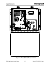
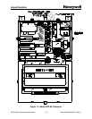
2.2.1 Master Controller Configuration
There are a number of system control switches and configuration switch blocks (DIP
switches) on the Master Controller. The configuration switch blocks may have multiple
switches. Reference to the individual switches will be made by referring to the switch
block number followed by the number of the individual switch as labeled on the switch
block. For example, SW1 (Figure 2-10, Item 1, Page 2-25) has 5 individual switches.
The third switch from the left is labeled as #3 on the switch block and will be referred to
as SW1-3.