


Airport Systems
SG-60 High Intensity Strobe System 2-5 Manual EPM-00000019 Rev A
• SW3 – (Figure 2-11, Item 3, Page 2-26) Used to specify the ID number for
the Flashhead. Each Flashhead must be set with a unique ID number as
indicated on the installation drawings. There is a diagram next to the switch
showing the values for the switch. The ID number is the total of the values of
the switches set to OFF (negative binary). For example, to set ID #10, set
SW3-2 (value 2) OFF (down) and SW3-4 (value 8) OFF (down) for a total of
10 (2+8).
§ SW3-1 – Set to OFF (down) for value 1
§ SW3-2 – Set to OFF (down) for value 2
§ SW3-3 – Set to OFF (down) for value 4
§ SW3-4 – Set to OFF (down) for value 8
§ SW3-5 – Set to OFF (down) for value 16
• SW4 – (Figure 2-11, Item 5, Page 2-26) This is used for the terminating
resistor on the communications line.
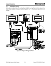
§ SW4-1 – Set to ON (up) for terminating resistor. This should be set ON
only for the Flashhead where the communication lines are terminated. In
a typical installation, the communications lines are terminated at the
Master Controller and the upper most Flashhead. In systems with an
AOL, the AOL is typically the upper most Flashhead. In systems without
an AOL, any one but only one of the Flashheads at the top level can be
set to ON. For all others, set to OFF. If the system is being installed in
stages as the tower is erected, SW4-1 should be set ON for one of the
flashheads at the highest installed level. As additional flashheads are
added at higher levels, adjust the configuration by setting SW4-1 to OFF
in the previous flashhead and set SW4-1 to ON for one of the flashheads
at the highest installed level.
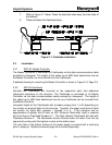
2.2.2.3 Flashtube Installation
The Flashheads are shipped from the factory without the flashtubes installed to prevent
damage during shipping. Install the flashtubes per the following procedure:
1. If Flashhead is already wired to AC power: Shut off the power to the system
by opening the main AC power circuit breakers.
2. Release the Flashhead cover latches.
3. Swing the cover open, exercising caution not to damage the glass face or the
gasket.
4. Unpack the flashtube. Do not touch the glass envelope - contamination from
a fingerprint will degrade the reliability of the flashtube.
5. Holding the flashtube by its metal ends, center it in the reflector assembly
and snap it into place. Make sure the red mark on the flashtube matches the
red mark on the socket assembly.
6. Attach the fast-on connector at each end of the flashtube to each socket
assembly. Make sure wires are not twisted - the metal to glass bond is fragile.