


Airport Systems
SG-60 High Intensity Strobe System 2-18 Manual EPM-00000019 Rev A
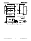
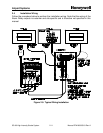
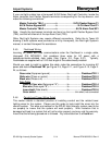
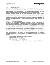
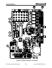
2.4.7 Junction Box Details
This section will detail the proper wire interconnection details for the input voltage and
data cable to the flashhead pigtail cable. These connections are very important to the
proper operation of the lighting system. The flashhead pigtail contains all the wires
required for proper interconnection between the conduit wiring and flashhead.
Additional reference materials can be found on the High Intensity Lighting system
drawing set. Please reference the below information and drawings for a proper
installation. Mis-wiring of these wires will not allow the flashheads to operate properly.
Please call the Honeywell Technical Support if you have any questions regarding the
installation of these connections. Systems that are improperly wired may void the
warranty.
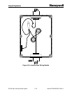
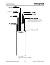
2.4.7.1 Flex Conduit Installation
On each of the high intensity flashheads, a pigtail is attached at the factory for
installation to the junction box. This pigtail may not be long enough for proper routing
along the horizontal and vertical struts on the tower. The high intensity lighting system
will have a 100-foot spool of pigtail cable, Honeywell P/N WC000001, for installer to
use for those flashheads that do not have a long enough pigtail. If this spool of cable
will not accommodate all the flashheads, extra cable can be ordered from Honeywell.
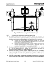
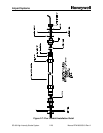
The ¾” flex conduit will be used for shielding of possible RF Interference generated by
some broadcast and radio towers. The conduit will be positioned over the flashhead
pigtail and connected at the junction box and flashhead enclosure by watertight
connector designed for the ¾” flex conduit. The installation will consist of the following
materials:
¾” Flex Conduit – Honeywell part number CL000002
¾” Sealing Ring – P/N *77-1085
¾” Bushing Insulator – P/N *77-1087
¾” Flex Conduit Fitting – P/N CD000003
Consists of: Gland nut, body, edge cone, nylon seal ring, and ¾” locknut
Please reference Figure 2-7, Page 2-20 for proper installation of this conduit.