


Airport Systems
SG-60 High Intensity Strobe System 3-4 Manual EPM-00000019 Rev A
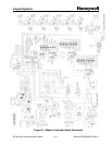
The Digital Board functions are discussed in more detail below.
3.2.2.1 Power Supplies
The Digital board rectifies (DB1) and filters (C4) the 24VAC output of the Flashhead T2
transformer, and uses the resulting unregulated voltage to power the K1, K2, and K3
relays. The K3 relay coil is wired directly to this supply. K3 will be energized whenever
power is supplied to the digital board. Power to the K1 and K2 relay coils is controlled
by the micro-controller.
The unregulated power that feeds the relays is regulated by VR1 to +15VDC. This is
used to power the logic and control circuitry on the Trigger/High-Voltage Board.
(Connection between the boards is made by traces on the Motherboard.)
The Digital board also rectifies (DB2) and filters (C5) one of the 12VAC outputs of the
Flashhead T2 transformer. This unregulated voltage is supplied to the power down
circuit (described below), and VR2. VR2 provides regulated 5V power to the
microcontroller and other logic chips. When 5V logic power is present, DS1 turns on
(red).
The power-down circuit can briefly shut down the input to VR2, effectively removing all
logic power from the board. The power-down logic has its own independent 5V power
(using simple zener diode regulation of the DB2/C5 output). The shutdown circuit does
not affect the relay or +15V supplies (although the K1 and K2 relays cannot be
energized as long as the micro-controller is unpowered). You can test the function of
the power-down circuit by pressing the S1 pushbutton for about 1 second. You should
see DS1 turn off momentarily, and then as DS1 turns back on, you should see the LED
check as the microcontroller software initializes (DS2 and DS3 should quickly blink
together twice).
3.2.2.2 Communications
The Digital Board receives commands from the Master Controller via an RS485 serial
link. The RS485 transceiver chip U11 is protected from voltage transients by surge
suppression devices and by transformer/optical isolation from chassis ground and the
rest of the digital board.
If a voltage transient destabilizes the communications hardware or the main processor,
the Digital Board will remove and restore its own logic power, thus clearing any
momentary hardware (or software) faults. See 3.2.2.1 above for more information on
the power down circuit.
SW4-1 (TERM) provides the necessary termination resistance for the RS485 serial
network. Each end of the cable should be terminated with a resistor. Typically, only
one flashhead (one of the ones farthest from the Master Controller) will have SW4-1
set to ON. All other flashheads will have SW4-1 set to OFF.
Every Flashhead must be assigned a unique address or ID (flashhead number) from 1
through 24 inclusive, so the Master Controller can monitor the status of each individual
Flashhead. The Flashhead number is set using SW3. Set the SW3 switches so that
their total value equals the desired flashhead number. The value for each switch