Airport Systems
SG-60 High Intensity Strobe System 2-28 Manual EPM-00000019 Rev A
6. Verify open circuit between TB5-S and TB5-A (both on Data Cable)
7. Verify open circuit between TB5-S and TB5-B (both on Data Cable).
8. In one of the top-most Flashheads, install a jumper (or alligator clip)
between TB1-5 and TB1-6.
9. Verify short circuit between (<20 ohms) TB5-S and TB5-B (both on Data
Cable).
10. Remove the jumper between TB1-5 and TB1-6.
11. Verify open circuit between TB5-S and TB5-B (both on Data Cable)
12. On the Master Controller card, measure between TB5-A and TB5-B and
verify 120 ohms +/- 10% resistance. If not, check for proper configuration.
See SW4 on page 2-5.
13. Plug Data Cable Connector TB5 back into PCB1.
14. Verify short circuit between TB5-S screw terminal and panel ground.
2.6 Power Up and System Tests
During the power up of the system, there are indicator lights which will be checked to
verify correct operation and installation. The following is a description of all the
indicators in the Master Controller and the Flashheads. The indicators in the
Flashhead need not be checked unless problems are encountered during the normal
power up tests.
2.6.1 Master Controller Status Indicators
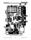
• Photo Mode Indicators (Figure 2-10, Item 3, Page 2-25)
§ DS25 – Red indicates active mode is Day
§ DS26 – Red indicates active mode is Twilight
§ DS27 – Red indicates active mode is Night
§ DS28 – Green indicates photocell is OK, Red indicates photocell is bad
• Individual Flashhead Status (Figure 2-10, Item 4, Page 2-25)
§ DS1-24 – Green indicates Flashhead is good, OFF indicates Flashhead
has not been selected for monitoring, Red indicates Flashhead is bad.
• Miscellaneous Indicators
§ DS34 – (Figure 2-10, Item 7, Page 2-25) ON indicates transmit OK
§ DS35 – (Figure 2-10, Item 9, Page 2-25) Flashing indicates sync input
read OK.
§ DS36 – (Figure 2-10, Item 10, Page 2-25) ON indicates red lights are
available, OFF indicates red lights are reporting alarm or not installed


