


Airport Systems
SG-60 High Intensity Strobe System 2-29 Manual EPM-00000019 Rev A
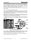
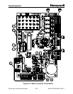
§ DS32 - 33 – (Figure 2-10, Item 5, Page 2-25) The indications on these
lights are dependent on the setting for external red light system on SW2.
If SW2-2 is set for an EXTERNAL RED system (ON), then
• DS32 – ON indicates there has been a red light system alarm
sometime during the night and the red light system is off, but will reset
the next day. OFF when in night mode and the red light system is not
in alarm
• DS33 – ON indicates in night mode, red lights are turned off and white
strobes are operating, OFF indicates NORMAL operation.
If SW2-2 is set for no EXTERNAL RED system (OFF) then
• DS32 – ON during DAY and TWILIGHT, OFF during NIGHT mode
• DS33 - Not used (lower right of board)
§ DS31 – (Figure 2-10, Item 5, Page 2-25) ON indicates power OK, OFF
indicates power failure
§ DS30 – (Figure 2-10, Item 5, Page 2-25) ON indicates photocell is
GOOD, OFF indicates photocell is BAD or not connected
§ DS29 – (Figure 2-10, Item 5, Page 2-25) ON indicates all Flashheads are
good, OFF indicates one or more Flashheads are bad
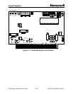
2.6.2 Flashhead Status Indicators
• Miscellaneous Indicators (Figure 2-11, Item 1, Page 2-26)
§ DS1 Red ON for 5-Volt logic power OK
§ DS2 Yellow ON for Flash Current Feedback OK
§ DS3 Green ON Steady for communications OK (receive & transmit)
OFF for no communications reception
Slow Blink (1/sec) for receiving but not being addressed to
transmit
Fast Blink (4/sec) for receiving, being addressed to transmit
but failing to transmit
2.6.3 System Power Up
All switches and indicators listed in this section are in the Master Controller, except for
the external system circuit breakers.
1. Verify POWER SWITCH is turned OFF.
2. Verify LOCAL / REMOTE switch is set to LOCAL.
3. Verify MODE switch is set to DAY.
4. Turn on circuit breaker to apply power to Master Controller.
5. Turn on circuit breaker to apply power to Flashheads.
6. Turn POWER SWITCH to ON.