


Airport Systems
SG-60 High Intensity Strobe System 2-22 Manual EPM-00000019 Rev A
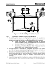
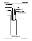
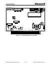
Item 6 is a shield drain wire that will not be used for interconnection. This wire should
be cut off flush from the cable when the outer jacket is stripped back for interconnection
of the system.
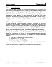
The following section is a guideline to a proper installation of the WC000001 cable.
Please follow this guideline to ensure a proper installation and interconnection in the
junction box.
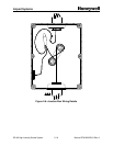
1. Strip back at least 16” of the outer jacket of the WC000001 cable. Make
sure that during this removal, the other wires are not damaged. If the
insulation is damaged on one of the other wires, a potential of lighting
problems can occur shortly after the system is connected.
2. Remove all the aluminum foils and braids from the exposed conductors.
These will not be used for interconnection.
3. Cut off Item #6, bare shield wire, that protrudes from the cable. This wire
will not be used for interconnection.
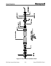
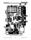
4. Connect Item #5, bare shield wire, and Item #4, #12-AWG Green wire,
from all the cables to the ground lug inside the junction box. This ground
lug can be found on the back plane of the junction box or at an internal
locknut that has a ground screw attached. No other wires will be
connected to ground.
5. Connect Item #1S, data/communication inner shield drain wire, to the
other data shield drain wires from the additional data cables. Trim back
the associated shield neatly. Make sure that this drain wire and the shield
cannot contact the walls of the junction box or other wires. Do not
connect inner shield to outer shield. Extra taping may be required for
proper isolation. The inner shield should only have a connection to
ground inside the SGC-60 controller.
On a typical installation, there will be a total of 5 wires that will be
connected together. One from the lower junction box level, three from the
flashhead cables on that level, and one for the cable going to the next
level.
6. Connect Item #1A to corresponding wires in other four cables as stated
above in step 5.
7. Connect Item #1B to corresponding wires in other four cables as stated
above in step 5.
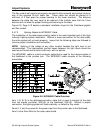
8. Connect the #12-AWG Black and #12-AWG White wires as required by
the installation drawing set supplied with the lighting system. If the
system has a 3-phase input, ensure proper connection between the
3-phase wires (typically brown, orange, and yellow) and the black and
white wires from the flashhead. Proper load balancing is required on the
three-phase input to operate efficiently (distribute the flashheads as
evenly as possible across the phases).