


Airport Systems
SG-60 High Intensity Strobe System 3-8 Manual EPM-00000019 Rev A
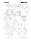
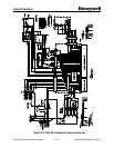
3.3 SGC-60 Master Controller
3.3.1 Power Supply
The Master Controller input power is connected to PB1, which then feeds transformer
T1 (under the switch panel). The Master Controller can accept a number of input
voltages, depending on the primary tap connections to T1, and will operate at 50 or 60
Hz. The T1 transformer output provides 12VAC to the Master Controller circuit board
PCB1 (T1-17 and T1-18 connecting to PCB1 TB1-1 and TB1-2). The input voltage
passes through fuse F1, is rectified by DB1, and filtered by C16.
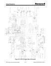
This unregulated voltage (about 16VDC) is available for external use TB8. The 16VDC
is also fed into the switch mode power supply (including voltage regulator VR1), which
provides regulated +5VDC to the rest of the board.
The 16VDC is also used to provide power for the power-down circuit. The power-down
circuit can briefly shut down the regulated +5VDC supply powering the rest of the board
logic, providing a power-on reset for the rest of the board logic.
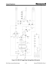
The power-down circuit will be activated automatically if (1) the microcontroller stops
functioning normally, or (2) the microcontroller detects a severe communications
failure. To prevent nuisance alarm chatter, the microcontroller will only deliberately
activate the power-down circuit if at least 24 hours have elapsed since the last power
on.
The power-down circuit is intended to allow automatic recovery from rare cases when
transients lock up the communications transceiver, but it can also be used as a manual
board reset. . You may test this function by holding down the RESET toggle switch on
the switch panel for about 1 second.
If input power is lost, or fuse F1 is blown the Power Fail Relay (K4, terminals TB3-C3,
-NO3, -NC3) will de-energize.
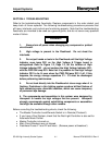
3.3.2 Flash Requests and Flashhead Status
The Master Controller transmits a flash request command to the Flashheads every 1.5
seconds (or every 1.0 seconds in Catenary mode, selected with SW2-1). The flash
request also contains the requested operating mode. The flash request applies to all
Flashheads, but is addressed to a specific Flashhead.
All Flashheads receive the flash request. All Flashheads flash in response to the
request, and update their operating mode, but only the addressed Flashhead may reply
to the Master Controller.
Whenever a the Flashhead replies OK, the Master Controller marks it as good, and
sets the corresponding Flashhead Status LED to green.
If the Flashhead does not reply OK, the Master Controller marks it as bad, and sets the
corresponding Flashhead Status LED to red.