


Airport Systems
SG-60 High Intensity Strobe System 2-2 Manual EPM-00000019 Rev A
2.2.1.1 System Controls
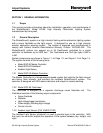
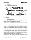
Set Master Controller switches (Figure 1-1, Page 1-2) as follows:
POWER SWITCH -------------------------------------------------------------------------- OFF
LOCAL / REMOTE Switch ------------------------------------------------------------ LOCAL
MODE Switch ------------------------------------------------------------------------------- DAY
The Master Controller has the following control switches (Figure 1-1, Page 1-2):
• POWER SWITCH: Toggle switch that turns input AC line power on/off in the Master
Controller. Does not affect AC power to the Flashheads. Input voltage is present at
terminal block PB1, even with the power switch turned off.
• RESET Switch: Momentary pushbutton that resets the Master Controller. Switch
must be held for about one second to activate.
• REMOTE / LOCAL Mode Switch: Two-position toggle switch that permits manual
(local) selection of the flash intensity level using the DAY / TWILIGHT / NIGHT
rotary switch. In normal (remote) operation, permits automatic operation controlled
by the Ambient Light Sensor photocell.
• DAY / TWILIGHT / NIGHT Switch: Three-position rotary switch that allows manual
selection of three light intensities of the system (DAY = high, TWILIGHT =
intermediate, and NIGHT = low). The REMOTE / LOCAL Mode Switch must be in
the LOCAL position to use this switch.
2.2.1.2 Power Configuration
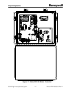
The input voltage selection is set at the factory prior to shipping. The user shall verify
the correct voltage as indicated by the label by Power In terminal block PB1 (Figure
1-1, Page1-2). If the voltage listed on the label does not match the voltage at the site,
contact Tech Support at (805) 581-5591.
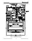
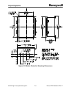
2.2.1.3 Configuration Switches
• SW1 – (Figure 2-10, Item 1, Page 2-25). This switch is used to set the
number of Flashheads (including antenna obstruction light (AOL)) in the
system up to 24. If the switches are set for more than 24 the system will still
monitor only 24 Flashheads. The number of lights configured equals the sum
of all the switches set to ON (positive binary). For example, to configure for
10 Flashheads, set SW1-4 (8 lights) to ON and SW1-2 (2 lights) to ON for a
total of 10 (8+2) lights.
§ SW1-1 – Set to ON (up) for 1 light
§ SW1-2 – Set to ON (up) for 2 lights
§ SW1-3 – Set to ON (up) for 4 lights
§ SW1-4 – Set to ON (up) for 8 lights
§ SW1-5 – Set to ON (up) for 16 lights