


Airport Systems
SG-60 High Intensity Strobe System 3-7 Manual EPM-00000019 Rev A
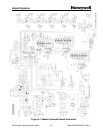
3.2.3.1 High Voltage Rectification
This section of the Trigger/High-Voltage Board provides the DC to charge the energy
storage capacitors that power the flashtube.
The high voltage AC from the ferro-resonant power transformer T1 pins T1-7 and T1-8
is output to the Trigger/High-Voltage board through the Flashhead motherboard pins
E5 and E6, respectively. The high-power diode bridge DB1 rectifies the incoming
2000Vp-p voltage to pulsed 2000VDC. This DC voltage is sent to charge the energy
storage capacitors through Flashhead motherboard pins E7 (+) and E4 (-). Voltage
divider circuit R6 - R10 with a series neon lamp, High Voltage Indicator DS1, is
connected to the bridge output. High Voltage Indicator DS1 lights whenever high
voltage is present.
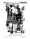
3.2.3.2 Flashtube Triggering
The trigger control section receives +15V power from the Digital Board. The Digital
Board also provides the trigger request signal telling the Trigger/High-Voltage Board to
fire the flashtube.
The heart of the Trigger circuit consists of a trigger capacitor C4, SCR Q4, and
unijunction transistor Q3. The trigger circuit energy is derived from terminals T1-6 and
T1-2 of transformer T1 through a rectifier circuit in the trigger control section. This
trigger energy is stored in a 0.5µF capacitor C4, whose charge path is through the
primary coil of the high voltage trigger transformer T2 to ground.
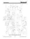
Microcontroller U1 synchronizes the actual flashtube firing more precisely with the high
voltage zero crossing. It buffers incoming trigger requests from the Digital Board, and
U1 pin 9 receives the trigger request signal from Digital Board U3 (about a 500µsec
low). U1 waits for a high-voltage zero crossing to pass, and then drives pin 10 is high
to charge C3. As soon as U1 detects the next high voltage zero crossing on pin 6, it
drives pin 10 low for 500µsec. This momentarily forces the gate of Q3 below the anode
of Q3, triggering Q3, a snap-action unijunction switch. C3 discharges through Q3 with a
fast rising current, driving the gate of SCR Q4. SCR Q4 then turns on, switching 0.5µF
capacitor C4, charged to 450 volts, into the primary coil of the series trigger transformer
T3, located on the flashtube assembly. The series trigger transformer T3 steps the
pulse to approximately 15KV, flashing the flashtube V1. The recharge current for the
capacitor C4 is limited by a series resistor to a value below the hold-in current of the
SCR Q4 so that it turns off, allowing capacitor C4 to charge again in time for the next
flash.
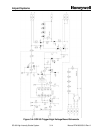
If another trigger request signal has arrived from the Digital Board, C3 is immediately
charged and the process is repeated until all trigger requests are processed.
The Trigger/High-Voltage Board will only fire the flashtube in response to a trigger
request from the Digital Board. For night flashes composed of multiple pulses, the
Trigger/High-Voltage Board requires a series of requests from the Digital Board.
If the U1 microcontroller cannot detect the high-voltage zero crossing, it will fire the
flashtube immediately after receiving the trigger request from the Digital Card.